Do you have a question about the Emerson ZX and is the answer not in the manual?
| Brand | Emerson |
|---|---|
| Model | ZX |
| Category | Air Conditioner |
| Language | English |
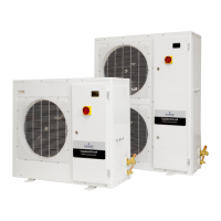
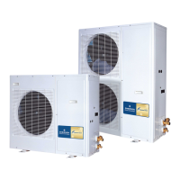
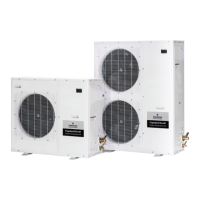
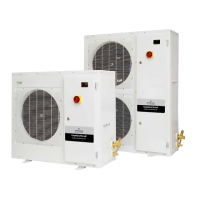
Details the application range and models of the ZX Condensing Unit.
Outlines the standard components and optional packages for the ZX CDU.
Illustrates and labels the components of the E2 control board.
Shows the Defrost Module and its connections.
Presents the Diagnostic Module, highlighting its features and variations.
Explains the Automatic Liquid Injection and other protection features.
Details the Diagnostic Module's LED status and interpretation chart.
Chart correlating LED status to system events and faults.
Highlights the affordability, low noise, and built-in technology benefits.
Summarizes the key value propositions of the ZX CDU.
Lists various installation types where the ZX CDU can be applied.
Explains the coding system used for ZX unit model identification.
Diagram labeling major components within the ZX unit.
Detailed view of the fan and motor assembly.
Illustrates the placement of HP and LP pressure switches.
Shows the patented liquid injection system during assembly.
3D views of component layout, not for dimensioning.
Illustrates the physical dimensions and clearance requirements for the unit.
Illustrates a four-port charging manifold, a key installation tool.
Depicts an electronic vacuum gauge, essential for system evacuation.
Step-by-step guide for initial pressure testing using vacuum and nitrogen.
Illustrates Schrader valves with and without depressors.
Procedure for leak testing using refrigerant and nitrogen pressurization.
Detailed steps for evacuating the refrigeration system.
Steps for charging the system with refrigerant and commissioning the unit.
Details the automatic liquid injection system for compressor protection.
Describes the fan speed control option and its benefits in low ambient conditions.
Explains the self-diagnostic capabilities of the Diagnostic Module.
Details the time-initiated, time-terminated defrost control module.
Covers compressor phase reversal, voltage, current, and pressure protections.
Explains how to set up the E2 controller for specific ZX unit models.
Details the E2 board's protection mechanisms for the compressor motor.
Covers high and low pressure protection mechanisms for the compressor.
Explains how discharge temperature protection is achieved via liquid injection.
Describes inputs like thermostat, case temperature, and ambient sensors.
Details the function of condenser coil and ambient air thermistors for fan control.
Lists outputs from the E2 board for solenoid valves and contactors.
Explains the operation and fault status display of the Diagnostic Module.
Covers external buzzer, dialer, and liquid floodback warning outputs.
Details the defrost module's settings for interval and duration.
Illustrates the Defrost Module and its control switches.
Shows the Diagnostic and Defrost modules connected to the E2 controller.
Guidance on cleaning condenser fins to maintain performance.
Recommendations for checking electrical connection tightness.
Information on the E2 control panel and fuse, noting it's not routine maintenance.
Procedures for routine leak testing of the system joints.
Table linking discharge/suction pressure issues to potential causes.
Guides technicians on system parameters for diagnosing issues.