S1CG/S1HG
in
le-Zone,
S2CG/S2H
Dual-Zone
•
nstallation,
eration and Maintenance Manual •
P/N 240007754, Rev. C [3/19/2010] 11 Made in the USA
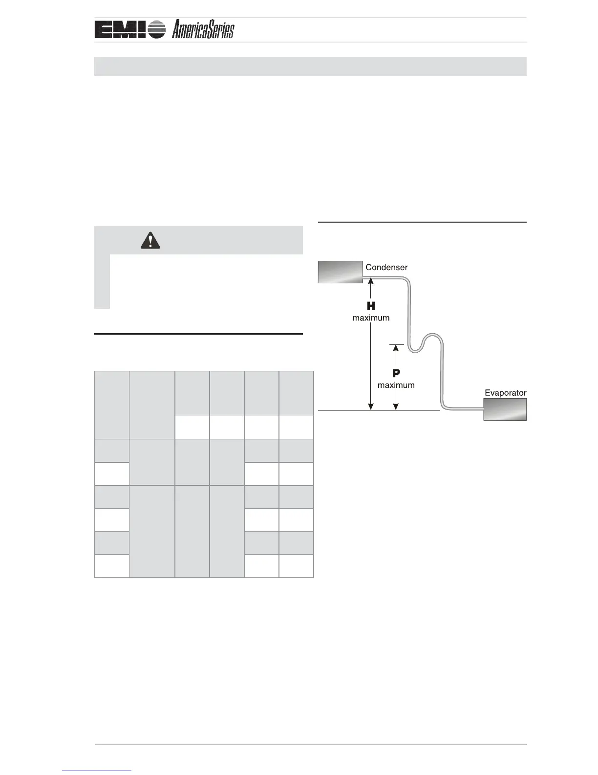
Refrigerant Piping
Tubing specifi cations
e system will support refrigerant runs to
the inside unit as listed in
Table 1, Page 11 .
e units are furnished with sweat connec-
tions and are equipped with refrigerant valves
and Schrader ings for charging and taking
pressure readings.
CAUTION
It is recommended that a fi lter drier be
installed in the liquid line, at the indoor
unit on models without a factory-in-
stalled lter drier (i.e. 18K and larger).
S1CG/S2CG tubing specifi ca-Table 1
tions (see Table 14, Page 11 )
Model Max.
Length
Equivalent
Feet
Max.
Lift
Max.
Trap
Height
Liquid
Line
Suction
Line
“H” “P” O.D. O.D.
09
50’
(15 m)
20’
(6 m)
15’
(5 m)
1/4" 1/2"
12 1/4" 1/2"
18
100’
(30 m)
35’
(11 m)
20’
(6 m)
3/8" 5/8"
24 3/8" 3/4"
30 3/8" 3/4"
36 3/8" 3/4"
P-trap installation
A P-trap is recommended when the •
suction riser is equal to or greater than
show in Figure 14, Page 11 and Table 1,
Page 11.
When the condenser is installed above the •
air handler, the P-trap will help the return
of oil back to the compressor.
P-trap placement (see Figure 14 Table 1,
Page 11 for dimensions H & P)
A P-trap may be fabricated using (2) street •
elbows and (2) regular elbow.
A prefabricated trap may be purchased •
from a wholesaler or distributor however
the trap should be shallow as with the (3)
elbow con guration.
Each elbow is approximately 2 equivalent •
feet.
One P-trap is equal to approximately •
12 equivalent feet.
P-traps are not required at the foot of the •
hot gas risers due to increased oil ow at
higher temperatures.
 Loading...


