S1CG/S1HG
in
le-Zone,
S2CG/S2H
Dual-Zone
•
nstallation,
eration and Maintenance Manual •
P/N 240007754, Rev. C [3/19/2010] 13 Made in the USA
Refrigerant Processing
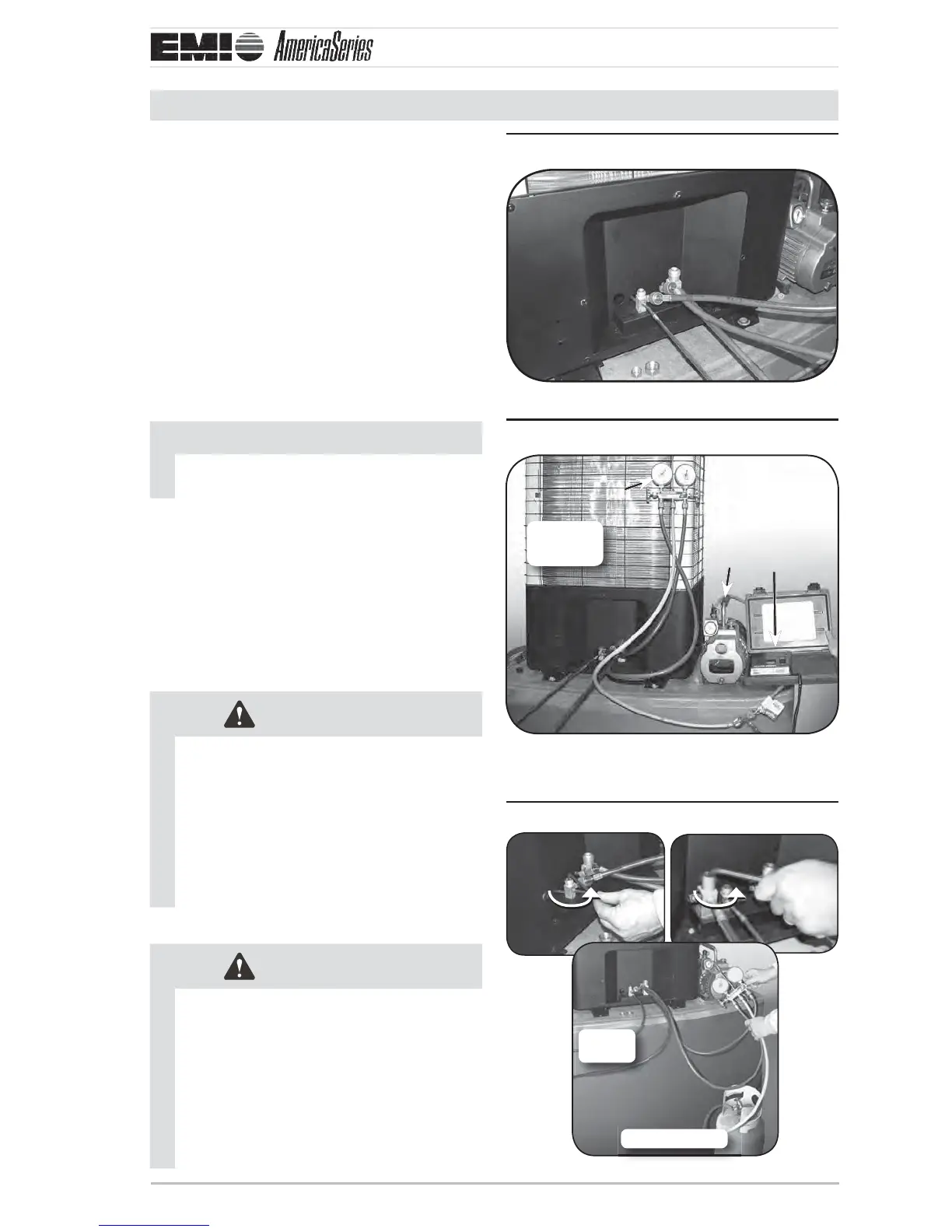
Charging the unit
A ach manifold set, vacuum pump, & 1.
Micron Gauge. ( Figure 18 ).
Evacuate line to 500 microns or less to 2.
ensure all moisture has been removed and
there are no leaks (Figure 19).
Once certain of a good evacuation and 3.
leak free joints, back-seat the valves
(counter-clockwise) to open and allow
factory charge to ll lines and indoor unit
(Figure 20, pg. 13).
NOTICE
Refer to refrigerant charge table for speci-
ed charge.
Charge to proper weight, charge based 4.
on feet of interconnect (see tables on
page 15 ). Only add/remove 410A in
liquid form.
Refer to charts beginning on 5. page 17 to
“ ne tune” the refrigerant charge to meet
your conditions.
CAUTION
All systems require eld charge adjust-
ments. Refer to the “Refrigerant Charge
Tables” for proper weight charge and
to the supplied “Single-zone Operation
Charts” for proper system pressures and
temperature at di erent outdoor condi-
tions. Superheat should be used for nal
system charge.
CAUTION
Charging should be done with a dial-a-
charge or weighed in with a scale.
When charging and checking pressures/
temperatures on system supplied with
Low Ambient Option, the fan cycle
switch should be jumpered out of the
circuit temporarily to obtain accurate
data.
Manifold set connections at unitFigure 18
S1CG
Shown
Manifold set up for evacuationFigure 19
A
B
C
S1CG
Shown
ManifoldA Vacuum pumpB
Micron gageC
ChargingFigure 20
S2CG
S1CG
Refrigerant
S1CG
Shown