S1CG/S1HG
in
le-Zone,
S2CG/S2H
Dual-Zone
•
nstallation,
eration and Maintenance Manual •
Comfort where it counts 32 P/N 240007754, Rev. C [3/19/2010]
Single-zone and Dual-zone Condenser Sequence of Operation
Testing Defrost Operation Using Test Pins
to rise within the condenser coil to melt o
any ice build-up. At the same time the unit
will switch on the indoor electric strip heater
to temper the cold air being discharged from
the air handler. is will continue until either
the defrost-sensor opens (approx. 60°F) or a
10-minute maximum cycle time has elapsed.
Defrost times will vary depending on outdoor
temperature and moisture conditions. When
the defrost cycle is complete the unit will return
to normal heating operation.
WARNING
Before removing the access panels to the
unit make sure that all power is discon-
nected from the unit. Failure to do so could
result in injury or electric shock.
Defrost operation can be initiated using the
test pins located on the circuit board of the
condensing unit. “Defrost test operation” will
be a time compressed version of the actual
defrost cycle.
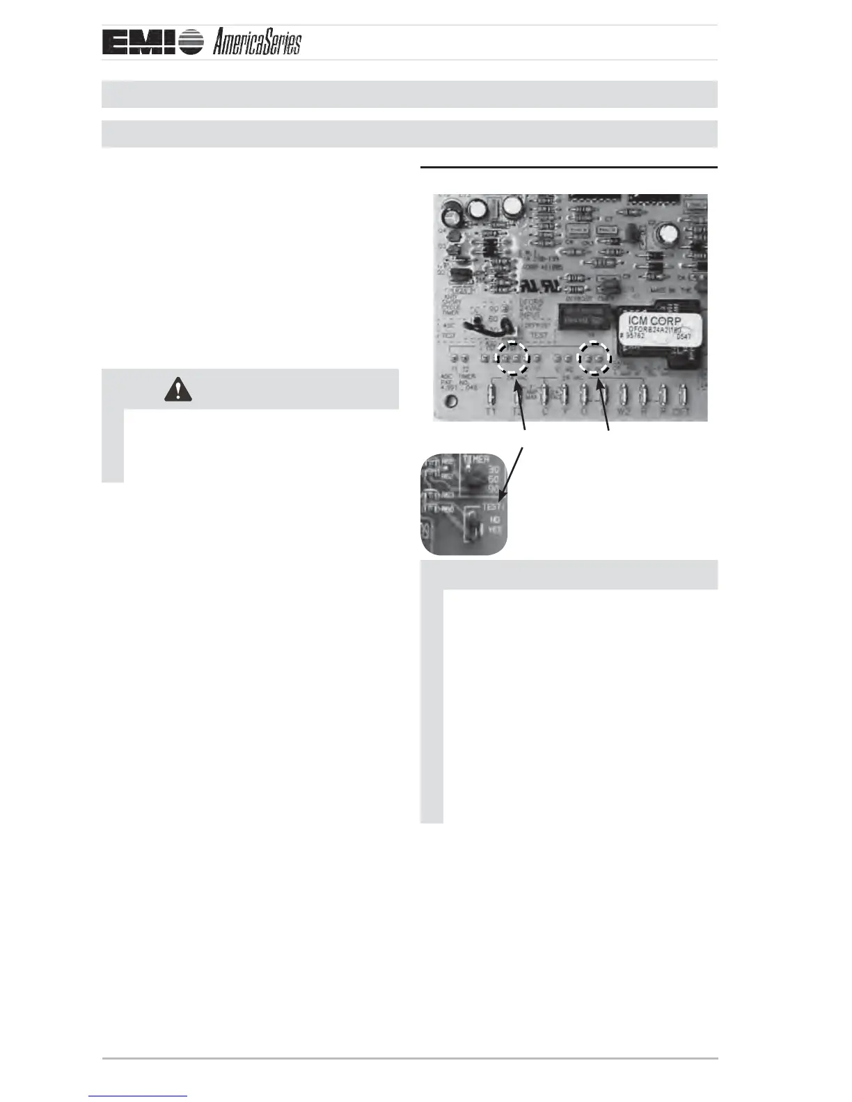
With the system “o ”, using two small alligator
clips, jumper the following sets of test pins. “R
and DF2” and “DFT TST”.
Defrost control board
Apply power to the indoor and outdoor units.
Place the indoor unit in heating mode with the
set point temperature well above room tem-
perature. is is to ensure that the condenser
will remain on during the entire defrost test
operation.
e condenser will operate in heating for ap-
proximately 20 seconds. At that point the unit
will enter defrost mode for approximately 2
seconds. During this time the condenser fan
will switch o , the reversing valve will energize
and the defrost board will energize the indoor
electric heat relay through the “W” terminal.
A er the two second defrost cycle is complete,
the unit will switch back to heating operation
for another 20 seconds. is process will re-
peat until the jumpers are removed from the
test pins.
NOTICE
If the condenser coil is heavily frosted
up with ice, it is likely that the “Defrost
Sensor” is already closed. In this case the
“R and DFT” jumper can be eliminated.
To initiate defrost, momentarily jump
pins marked “DFT TST” until the defrost
cycle begins. The unit will remain in
defrost mode until the condenser coil is
defrosted and then it will return to heat-
ing mode. When testing is complete be
sure to remove the jumper(s). DO NOT
leave the unit in test mode with jumper(s)
in place.
Low ambient operation
If the unit is equipped with low ambient fan con-
trol for cooling, the fan will remain o (while
in cooling mode) until the condenser pressure
reaches 340 psi. e fan will then energize and
run until the condenser pressure falls below
247 psi. is will happen only in the cooling
mode (or when the reversing valve is energized).
In heating (reversing valve not energized), the
fan will run continuous so long as the connec-
tion is made between “R” and “Y”.
Defrost control board Figure 21 (S1H shown)
DFT TST
R and DF2
S2HG