S1CG/S1HG
in
le-Zone,
S2CG/S2H
Dual-Zone
•
nstallation,
eration and Maintenance Manual •
Comfort where it counts 8 P/N 240007754, Rev. C [3/19/2010]
Electrical Wiring
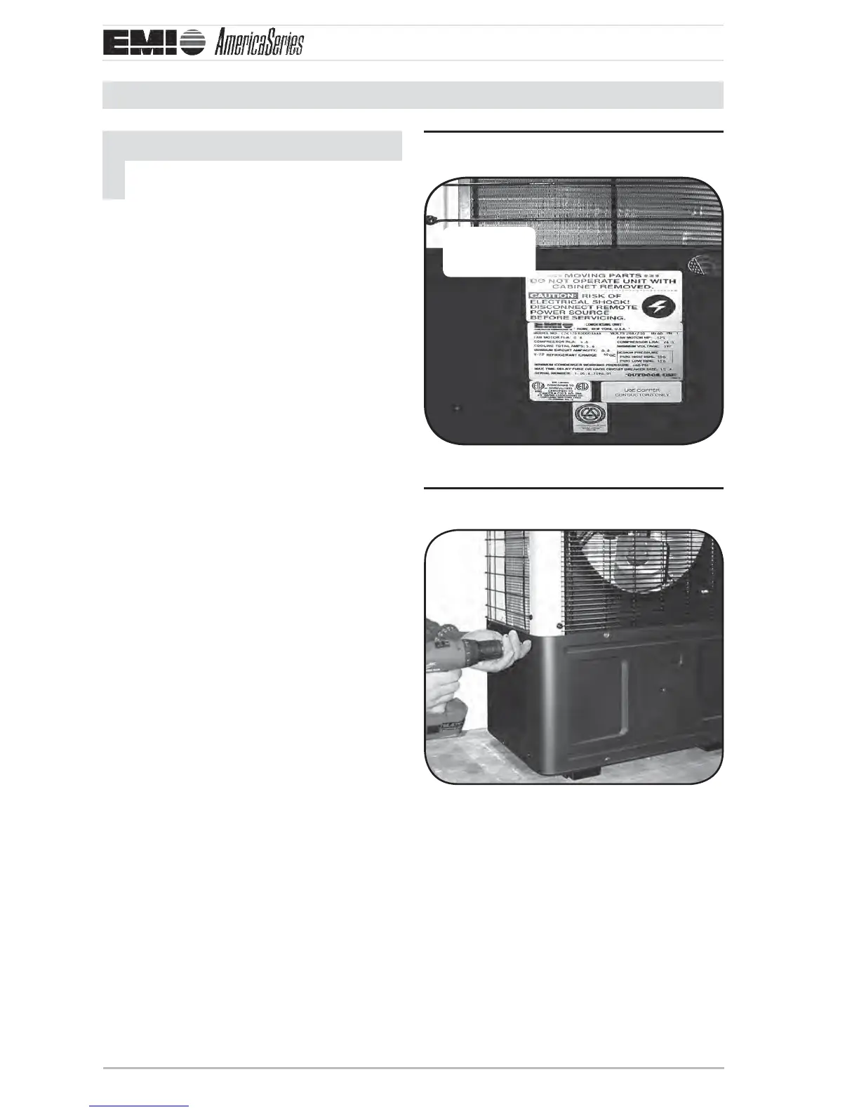
Rating plate locationFigure 5
Rating
plate
Remove side panel screwsFigure 6
NOTICE
All electrical wiring must be run accord-
ing to NEC and local codes.
1. Figure 5, Page 8 — Refer to the unit rat-
ing plate for voltage, minimum circuit
ampacity and over current protection
requirements.
Use only HACR type breakers or time 2.
delay fuses. Select the wire size according
to the ampacity rating.
To access electrical connections and wir-3.
ing diagram:
a. Figure 6, Page 8 — Remove the
screws on the side panel that covers
the electrical box. e box is adjacent
to the back panel and denoted with
electrical connections.
e screws adjacent to the front panel b.
should already be loose (don’t remove
them).
Slide the side panel out to access the c.
high/low electrical connections and
wire diagram.
d. Figure 7, Page 9 — Add water-tight
strain relief ing to the high volt side
before wiring, a split grommet ing
has been factory installed in the low
volt side.
Power should be run to a weather proof 4.
disconnect box usually within 3 feet of
the unit.