S1CG/S1HG
in
le-Zone,
S2CG/S2H
Dual-Zone
•
nstallation,
eration and Maintenance Manual •
P/N 240007754, Rev. C [3/19/2010] 9 Made in the USA
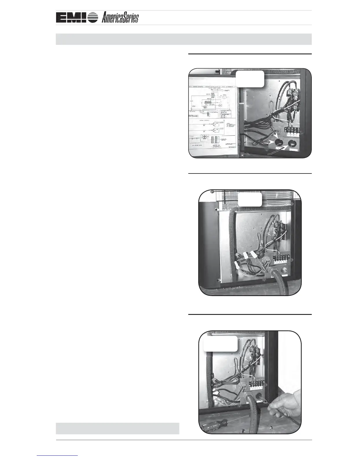
Electrical Wiring (continued)
Power entrancesFigure 7
S1CG
Shown
High volt
Plastic edge guards
Low volt
High voltage connectionsFigure 8
S1CG
Shown
Low voltage connectionsFigure 9
S1CG
Shown
Continued on next page
5. Figure 8, Page 9 — From the disconnect
box, run the power through the 7/8”
hole on the side of the unit and into the
electrical box. Anchor with the strain
relief ing.
Run wires to the high volt pigtail in the 6.
control box and a ach L1 and L2 con-
nections. Also run green wire to ground
wire.
Check wiring diagram for the required 7.
number of low voltage wires to be run
between indoor and outdoor sections.
8. Figure 9, Page 9 — Connect the 24 volt
wiring matching color to color. Refer to
the wiring diagram on the inside panel of
the condenser, and also refer to the wir-
ing diagram on the indoor unit. Low volt
interconnect should be at least 18 awg.
See 9. Figure 10, Page 10 and Figure 11,
Page 10 for completed wiring of S1CG
and S2CG examples.
To replace side panel slide the slotted 10.
holes of the panel onto the loosened
screws of the front panel so that the edge
of the front panel covers the edge of the
side panel.
Fasten all remaining loose screws.11.