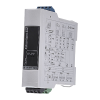
Switch point optimisation is switched on or off using the operating elements on
the FEC 22.
Procedure
• Turn the rotary switch to
Position 2.
• When first delivered or
after a reset the extreme
left LED in the chain
lights up:
switch point
optimisation
de-activated.
• Press the right key.
• The extreme right LED in
the chain lights up:
switch point optimisation
activated.
Deactivating switch
point optimisation
Switch point optimisation can be de-activated (Procedure see Fig. 6.2).
The FEC 22 then operates with the capacitance stored in its memory (capacitance
when empty C
L
or capacitance when probe covered C
H
) and the calculated switch
point capacitance C
S
. The latter is no longer changed.
Current switch point
difference ∆CProcedure
• Turn the rotary switch to
Position 1.
• The current switch point
difference ∆C can be
read off on the LED
chain (Assigning values
see Fig. 6.3).
Note!
The current switch point difference ∆C (rotary switch in Position 1) can only be
displayed if:
• both calibrations (probe uncovered and probe covered) have been carried out
∆C = 0.5 x (C
H
- C
L
)
• a calibration when probe uncovered has been carried out and switch point
optimisation activated
∆C = C
S
-C
L
• a calibration when probe covered has been carried out and switch point
optimisation activated ∆C = C
H
- C
S
Note!
1
3
7
7
3
1
∆
c
∆
c
ONOFF
ON
ON
OFF
OFF
1x
2x
0x
BA160Y62
Activating switchpoint
optimisation
Fig. 6.2
Activating switch point
optimisation
1
3
7
∆c∆c
7
1
3
∆C∆C
<4
pF
4-8
pF
>32
pF
16-32
pF
8-16
pF
=
BA160Y63
Fig. 6.3
Display of current switch point
difference
∆
C
Elektronic insert FEC 22 6 Additional Settings
Endress+Hauser 35
 Loading...


