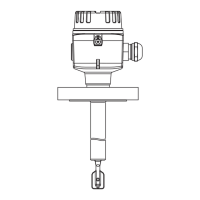
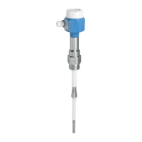
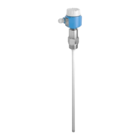
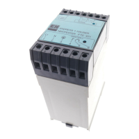
Electrical connection Liquiphant FTL51B
26 Endress+Hauser
Behavior of switch output and signaling
3 54
3 54
6 87
6 87
3 54
3
3
5
5
4
4
6 87
6
6
8
8
7
7
MAX
RD YE GN
MIN
A0033513
22 Behavior of switch output and signaling, electronic insert FEL64
MAXDIP switch for setting MAX safety mode
MIN DIP switch for setting MIN safety mode
RD LED red for alarm
YE LED yellow, switch status
GN LED green, operational status, device on
5.2.5 DC connection, relay output (electronic insert FEL64 DC)
• Switches the loads via 2 potential-free changeover contacts
• Two galvanically isolated changeover contacts (DPDT), both changeover contacts switch
simultaneously
• Functional testing without level change. Functional testing of the entire device can be
performed using the test button on the electronic insert or with the test magnet (can be
ordered as an option) with the housing closed.
Supply voltage
U = 9 to 20 V
DC
Observe the following as per IEC/EN61010-1: Provide a suitable circuit breaker for the
device, and limit the current to 500 mA, e.g. by installing a 0.5 A fuse (slow-blow) in the
supply circuit.
Power consumption
P < 1.0 W

 Loading...


