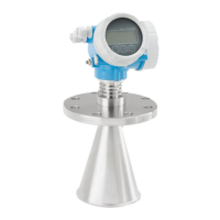
Micropilot FMR53, FMR54
Endress+Hauser 33
Performance characteristics
Reference operating
conditions
• Temperature = +24 °C (+75 °F) ±5 °C (±9 °F)
• Pressure = 960 mbar abs. (14 psia) ±100 mbar (±1.45 psi)
• Humidity = 60 % ±15 %
• Reflector: metal plate with a diameter ≥ 1 m (40 in)
• No major interference reflections inside the signal beam
Maximum measured error
Typical data under reference operating conditions: DIN EN IEC 61298-2 / DIN EN IEC 60770-1;
percentage values in relation to the span.
Device version Value Output
digital analog
1)
Standard Sum of non-linearity, non-
repeatability and hysteresis
± 6 mm (0.24 in) throughout the entire
measuring range
± 0.02 %
Offset/Zero ± 4 mm (0.2 in) ± 0.03 %
1) Only relevant for 4-20mA current output; add error of the analog value to the digital value
Measured value resolution
Dead band according to DIN EN IEC 61298-2 / DIN EN IEC 60770-1:
• Digital: 1 mm
• Analog: 1 μA
Response time
The response time can be configured. The following step response times (in accordance with DIN EN
IEC 61298-2 / DIN EN IEC 60770-1)
1)
are when damping is switched off:
Tank height Sampling rate Response time
< 10 m (33 ft) ≥3.6 s
–1
< 0.8 s
< 20 m (66 ft) ≥2.7 s
–1
< 1 s
Influence of ambient
temperature
The measurements are performed according to DIN EN IEC 61298-3 / DIN EN IEC 60770-1
• Digital (HART, PROFIBUS PA, FOUNDATION Fieldbus): average T
C
= 3 mm/10 K
• Analog (current output):
• Zero point (4 mA): average T
C
= 0.02 %/10 K
• Span (20 mA): average T
C
= 0.05 %/10 K
Influence of gas phase
High pressure reduces the speed of propagation of the measuring signals in the gas/vapor above the
medium. This effect depends on the type of gas phase and its temperature. This results in a
systematic measured error that increases with increasing distance between the reference point of
the measurement (flange) and the surface of the product. The following table shows this measured
error for a few typical gases/vapors (with regard to the distance, a positive value means that a too
large distance is measured):
Gas phase Temperature Pressure
1 bar (14.5 psi) 10 bar (145 psi) 50 bar (725 psi) 100 bar (1 450 psi) 160 bar (2 320 psi)
Air/nitrogen 20 °C (68 °F) 0.00 % 0.22 % 1.2 % 2.4 % 3.89 %
200 °C (392 °F) –0.01 % 0.13 % 0.74 % 1.5 % 2.42 %
400 °C (752 °F) –0.02 % 0.08 % 0.52 % 1.1 % 1.70 %
Hydrogen 20 °C (68 °F) –0.01 % 0.10 % 0.61 % 1.2 % 2.00 %
200 °C (392 °F) –0.02 % 0.05 % 0.37 % 0.76 % 1.23 %
400 °C (752 °F) –0.02 % 0.03 % 0.25 % 0.53 % 0.86 %
1) According to DIN EN IEC 61298-2 / DIN EN IEC 60770-1, the step response time is the time that elapses after an abrupt change in the input
signal until the change in the output signal has adopted 90% of the steady-state value for the first time.

 Loading...


