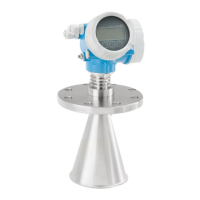
Micropilot FMR53, FMR54
Endress+Hauser 37
Measurement in a plastic vessel
If the outer wall of the vessel is made of a non-conductive material (e.g. GFRP) microwaves can also
be reflected off interfering installations outside of the vessel (e.g. metallic pipes (1), ladders (2),
grates (3) etc.). Therefore there should be no such interfering installations in the signal beam.
A0017123
Optimization options
• Antenna size
The larger the antenna the smaller the beam angle α, resulting in fewer interference echoes.
• Interference echo suppression (mapping)
Measurement can be optimized by electronically suppressing interference echoes
• Take into account the orientation of the antenna, the marking on the flange or threaded
connection
• A stilling well can be used to avoid interference influences
• Metallic plates mounted at an angle
These plates scatter the radar signals and can therefore reduce interference echoes.
Beam angle
A0016891
18 Relationship between beam angle α, distance D and beamwidth diameter W

 Loading...


