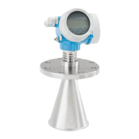
Micropilot FMR53, FMR54
Endress+Hauser 43
• If possible, avoid installation positions in which condensate or buildup can form between the
antenna and the vessel.
• In the case of outdoor installations, ensure that the area between the antenna and the tank is
protected from the weather.
• Do not install any fittings or attachments between the antenna and the tank that could reflect the
signal.
Suitable thickness of the tank ceiling:
Penetrated material PE PTFE PP Plexiglass
ε
r
2.3 2.1 2.3 3.1
Optimum thickness 16 mm (0.65 in) 17 mm (0.68 in) 16 mm (0.65 in) 14 mm (0.56 in)
Planar antenna (FMR54)
The planar antenna is only suitable for installation in a stilling well and cannot be mounted freely in
the vessel.
Installation in stilling well
A0016841
21 Installation in stilling well
1 Marking to align the antenna
• For the horn antenna: align the marking towards the slot.
• No alignment is required for planar antennas.
• Measurements can be performed through an open full bore ball valve without any problems.
• After mounting, the housing can be turned 350 ° in order to facilitate access to the display and the
terminal compartment.
Recommendations for the stilling well
• Metal (no enamel liner; plastic liner on request).
• Constant diameter.
• Stilling well not larger than antenna diameter.
• Difference in diameter between horn antenna and inner diameter of the stilling well as small as
possible.
• Weld seam as smooth as possible and on the same axis as the slot.
• Slot offset by 180° (not 90°).
• Slot width or diameter of holes max. 1/10 of pipe diameter, deburred. The length and number do
not affect the measurement.
• Select a horn antenna that is as big as possible. For intermediate sizes (e.g. 180 mm (7 in)) select
the next biggest antenna and adapt it mechanically (for horn antennas).
• At transition points, e.g. when a ball valve is used or individual pipe segments are joined, any gaps
that occur should not exceed 1 mm (0.04 in).

 Loading...


