Do you have a question about the Endress+Hauser Proline Promag H 500 and is the answer not in the manual?
Explains electrical, communication, and information symbols used in the manual.
Describes the electromagnetic measuring principle based on Faraday's law.
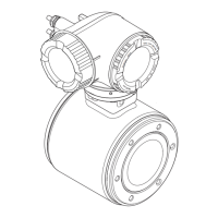
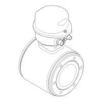
Details the two available transmitter versions, Proline 500 digital and Proline 500.
Covers IT security measures and device-specific security functions for safe operation.
Provides flow characteristic values in SI units for various nominal diameters.
Details available output/input options and their order codes.
Lists safety-related values for different output/input options and protection types.
States that low flow cut off switch points are user-selectable.
Shows terminal assignments for HART, FOUNDATION Fieldbus, and PROFIBUS PA.
Lists order codes for device plugs used with fieldbus systems.
Lists available supply voltage options and their terminal voltage/frequency range.
Illustrates the connection of the sensor and transmitter connecting cable for digital transmitters.
Shows terminal connections for the Proline 500 digital transmitter.
Provides connection examples for HART current output (active and passive).
Shows connection examples for PROFIBUS PA.
Illustrates connection examples for EtherNet/IP networks.
Illustrates connection examples for Modbus RS485.
Shows connection examples for pulse/frequency output.
Details requirements for ensuring correct measurement through potential equalization.
Covers permitted temperature range, power supply, protective ground, and signal cable specifications.
Explains how to choose connecting cables based on transmitter type and installation zones.
Outlines error limits and conditions for device calibration and measurement.
Provides guidance on preferred sensor installation locations and distances.
Discusses horizontal installation, electrode plane orientation, and empty pipe detection.
Specifies maximum permitted lengths for connecting cables based on fluid conductivity.
Details dimensions and procedures for post mounting the transmitter housing.
Specifies ambient temperature ranges for the transmitter and local display.
Lists IP ratings and vibration resistance specifications for the device.
Shows the operating range for medium temperature in graphical format.
Displays pressure-temperature ratings for stainless steel weld-in nipples.
Shows pressure-temperature ratings for ASME B16.5 flanges.
Shows pressure-temperature ratings for aseptic gasket seal connections.
Lists limit values for absolute pressure in mbar/psi for medium temperatures.
Details dimensions in SI units for the Proline 500 – digital transmitter housing.
Provides dimensions for the aluminum coated sensor connection housing.
Illustrates front view dimensions for sensor flange connections.
Details dimensions for aseptic female flanges according to DIN 11864-2.
Details dimensions for welding nipples with aseptic gasket seals.
Shows dimensions for Tri-Clamp connections.
Details dimensions for SC DIN 11851 threaded couplings.
Shows dimensions for wall mounting kits.
Discusses the external WLAN antenna and its suitability.
Details dimensions for external threaded connections.
Lists materials used for transmitter, sensor connection housing, and sensor.
Covers cable gland and adapter options and their materials.
Specifies materials for sensor housing, measuring tubes, liner, and process connections.
Details surface roughness requirements for various process connections.
Explains remote operation via HART protocol.
Shows HART protocol connection options for remote operation.
Illustrates remote operation via FOUNDATION Fieldbus network.
Details network topologies for EtherNet/IP.
Explains point-to-point connections via the CDI-RJ45 service interface.
Describes operating tools like Web browser for device access.
Explains HistoROM data management for reliable operation and servicing.
Details different data storage units and their contents.
States that the device meets applicable EU Directives and CE mark requirements.
Lists ATEX/IECEx Ex db protection types for transmitter and sensor.
Shows cCSAus hazardous area versions for IS and XP protection.
Details HART interface certification and requirements.
States that the device is certified and registered by ODVA for EtherNet/IP.
Describes available application packages to enhance device functionality.
Explains the electrode cleaning circuit (ECC) function for applications with magnetite deposits.
Lists accessories available for the transmitter, including WLAN antenna and mounting sets.
Details connecting cable options for sensors.
Describes the Applicator software for selecting and sizing measuring devices.
Refers to documentation for scope of technical documentation.
Mentions installation instructions for spare part sets and accessories.
| Measurement Principle | Faraday's law of electromagnetic induction |
|---|---|
| Housing Material | Aluminum, Stainless steel |
| Device Type | Electromagnetic flowmeter |
| Application | Liquids, Slurries |
| Lining | PTFE, PFA |
| Electrode material | Tantalum |
| Process Pressure | Up to 40 bar (depending on size) |
| Accuracy | ±0.2% of measured value |
| Output Signal | 4-20 mA, Pulse, Frequency |
| Digital Communication | HART, PROFIBUS PA, FOUNDATION Fieldbus |
| Power Supply | 100 to 230 V AC |
| Degree of Protection | IP67 |
| Material | Various materials depending on component |


 Loading...