Do you have a question about the Endress+Hauser Proline Promag P 100 and is the answer not in the manual?
Overview of safety, electrical, tool, and graphic symbols used in the document.
Explains symbols related to tools used for device installation and maintenance.
Details symbols indicating allowed, preferred, forbidden actions, and references.
Defines symbols used for item numbering, steps, views, and sections in graphics.
Specifies qualifications and authorizations for personnel performing tasks with the device.
Details the intended application and media compatibility for the measuring device.
Outlines safety measures for working on the device, including PPE, welding, and proper operation.
Confirms device safety and discusses IT security mechanisms and responsibilities.
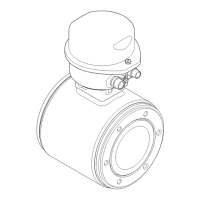
Introduces the physical components of the measuring device.
Details components for HART, Modbus, PROFIBUS DP, and EtherNet/IP communication types.
Guides the user through receiving and inspecting the device upon delivery.
Explains methods for identifying the measuring device, including nameplate details.
Provides guidelines for storing the measuring device to maintain its condition and integrity.
Offers safety warnings and instructions for safely transporting the measuring device.
Specifies general conditions, mounting positions, and orientations for the device.
Details precautions for installing the device in down pipes, partial fill, and sensor orientation.
Outlines ambient temperature, system pressure, and outdoor operation considerations.
Details measures to prevent vibration issues and information related to adapters.
Covers required tools, preparation steps, and sensor mounting procedures.
Instructions for seals, ground cables, screw torques, and a post-installation verification checklist.
Lists tools, cable specs, and requirements for power, signal, and communication interfaces.
Details pin configurations for various communication protocols and device versions.
Requirements for shielding and grounding to ensure EMC and explosion protection.
Steps for connecting the transmitter and ensuring equal electrical potential to prevent damage.
Illustrates connection scenarios for different pipe types and cathodic protection units.
How to configure device addresses (IP for EtherNet/IP, PROFIBUS DP) using DIP switches.
Enables/configures terminating resistors for PROFIBUS DP and other interfaces using DIP switches.
Steps to maintain IP66/67 and Type 4X enclosure protection after electrical connection.
A checklist to verify all electrical connections, settings, and grounds are correct.
Explains the device's operating menu structure and user role assignment.
Details accessing the device via web browser, prerequisites, login, and UI elements.
How to access the menu via operating tools and various service interfaces (CDI, RJ45).
Guides on operating via Ethernet and establishing EtherNet/IP connections using FieldCare.
Details on integrating EtherNet/IP devices into automation systems.
Emphasizes checks before commissioning and establishing FieldCare connection.
Steps for configuring device address via software and defining tag names.
How to enable write protection via access code or write protection switch.
How diagnostic events and remedial measures are displayed in web browser and FieldCare.
| Measurement Principle | Electromagnetic |
|---|---|
| Housing Material | Aluminum, Stainless steel |
| Pressure Range | Up to 40 bar (depending on nominal diameter) |
| Output Signal | 4-20 mA |
| Digital communication | HART |
| Lining | PTFE, PFA |
| Electrode material | Stainless Steel |
| Degree of protection | IP66/67 |
| Accuracy | ±0.5% of reading ± 1 mm/s (±0.04 in/s) |
| Temperature Range | -20 to +60 °C (ambient), -40 to +130 °C (process) |


 Loading...