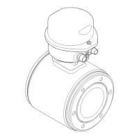
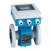
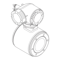
Do you have a question about the Endress+Hauser Proline Promag 10 and is the answer not in the manual?
Defines the intended application and outlines general operational safety guidelines.
Provides essential guidelines for device installation and operation.
Details procedures for returning devices and explains safety notes.
Describes device designation and details on transmitter and sensor nameplates.
Covers CE mark, declaration of conformity, and registered trademarks.
Procedures for receiving, transporting, and storing the device.
Specifies requirements for installation site and conditions.
Detailed steps for installing Promag sensors (W, P, H).
Checklist to perform after the device has been installed.
Covers connecting remote and measuring units, including cable termination.
Addresses potential equalisation methods and degree of protection requirements.
Final checks to perform after completing electrical installation.
Description of the local display and push buttons for operation.
Guide to the function matrix and basic operating procedures.
Details error messages, HART communication, and device status.
Ensures functional checks are complete before powering up the device.
Provides a guide to setup and procedures for commissioning the device.
Instructions for cleaning the device exterior and replacing seals.
Lists transmitters, cables, and grounding accessories.
Details mounting kits and various connection accessories.
Provides information on software and diagnostic tools.
Guides through troubleshooting steps and identifies error types.
Details error responses and procedures for replacing components.
Provides a history of software versions and modifications.
Summarizes application, system design, input, output, and power supply.
Details specifications for measuring tubes, including dimensions.
Provides information on the physical dimensions of the device.
Illustrates the structure of the Promag 10 function matrix.
Covers system units, operation modes, and user interface settings.
Details output configuration, pulse/status settings, and communication.
Provides details on sensor data, versions, and factory default settings.
| Device Type | Electromagnetic flowmeter |
|---|---|
| Measurement Principle | Electromagnetic |
| Lining | PTFE, PFA, rubber |
| Electrode Material | 316L stainless steel, Hastelloy |
| Process Pressure | Up to 40 bar (depending on nominal diameter) |
| Output Signal | 4 to 20 mA |
| Power Supply | 24 V DC |
| Ingress Protection | IP67 |
| Process Connection | Flange, clamp, threaded |
| Material | Stainless Steel |


