Proservo NMS80/81/83
12 Endress+Hauser
Use in protective systems
Device behavior during
operation
Digital
Device behavior during power-up
Once switched on, the device runs through a diagnostic phase of approx. 30 seconds. The relay
contact is open during this time. During the diagnostic phase, no communication is possible via the
service interface (CDI) or via protocols (HART, V1, Modbus).
Device behavior in safety function demand mode
The device displays a digital output value which corresponds to the limit value to be monitored. The
relay contact is closed within the range of validity, and is open outside this range. This must be
monitored and processed accordingly by a connected logic unit.
Device behavior in event of alarms and warnings
The relay contact is always open in the event of alarms and warnings. This must be monitored and
processed accordingly by a connected logic unit.
Alarm and warning messages
Additional information is provided by the alarm and warning messages in the form of error codes
and associated clear text messages.
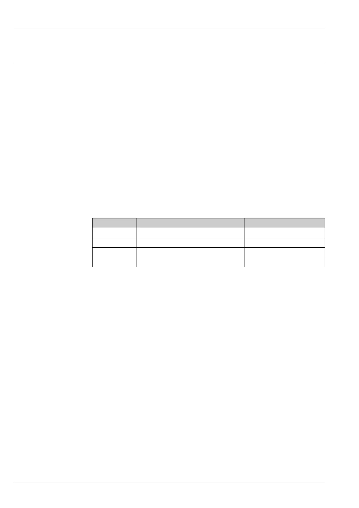
The following table shows the correlation between the error code and the relay contact output:
Error code
1)
Relay contact (message type) Note
Fxxx Open xxx = three-digit number
Mxxx corresponding to measuring mode xxx = three-digit number
Cxxx corresponding to measuring mode xxx = three-digit number
Sxxx corresponding to measuring mode xxx = three-digit number
1) The error codes are listed in the Operating Instructions.
Analog
Device behavior during power-up
Once switched on, the device runs through a diagnostic phase of approx. 30 seconds. The current
output is set to error current ≤3.6 mA during this time.
During the diagnostic phase, no communication is possible via the service interface (CDI) or via
protocols (HART, V1, Modbus).
Device behavior in safety function demand mode
The device outputs a current value corresponding to the limit value to be monitored. This value must
be monitored and processed further in a connected logic unit.
Device behavior in event of alarms and warnings
The output current on alarm can be set to a value ≤3.6 mA or ≥21.0 mA.
In some cases e.g. failure of power supply, a cable open circuit and faults in the current output itself,
where the error current ≥21.0 mA cannot be set, output currents of ≤3.6 mA occur irrespective of
the configured error current .
In some other cases (e.g. cabling short circuit), output currents of ≥21.0 mA occur irrespective of the
configured error current.
For alarm monitoring, the downstream logic unit must be able to recognize error currents of the
upper level for signal on alarm (≥21.0 mA) and of the lower level for signal on alarm (≤3.6 mA).

 Loading...


