Electrical connection Proservo NMS81
32 Endress+Hauser
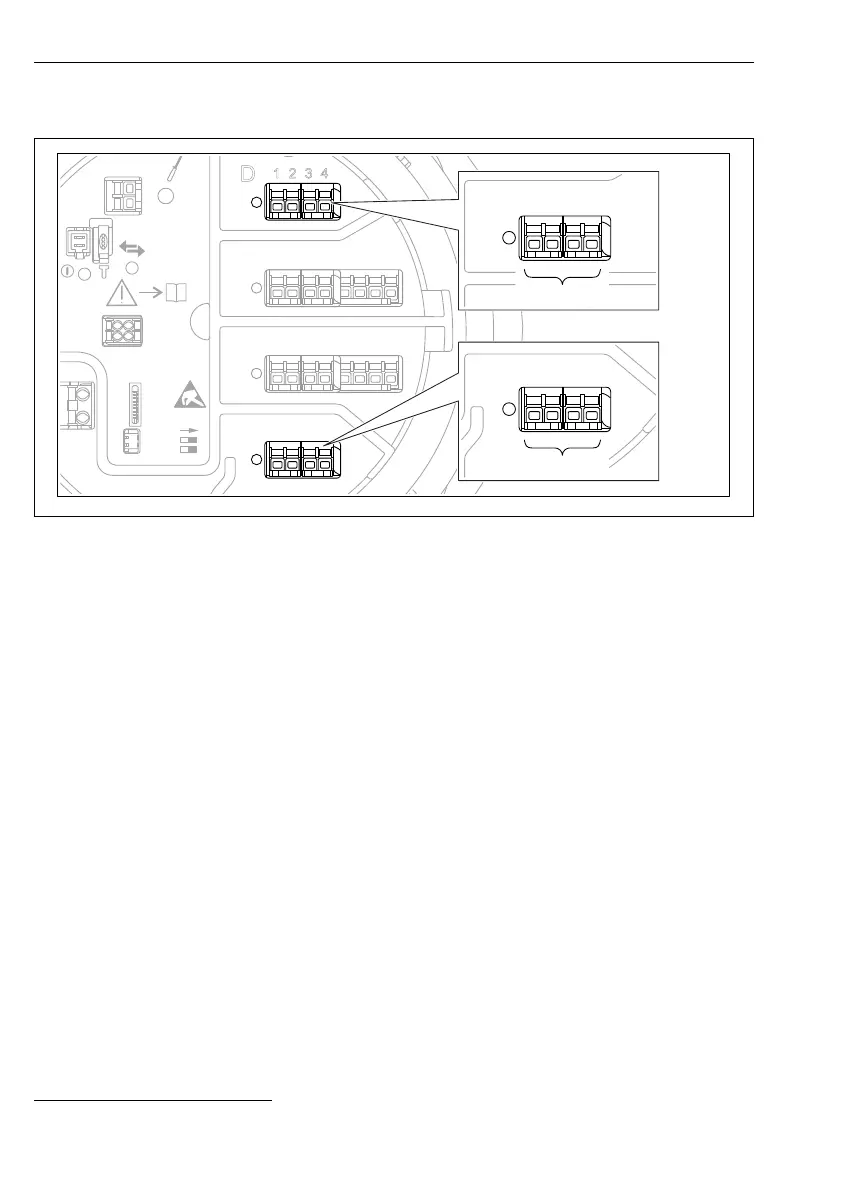
6.1.5 Terminals of the "Modbus" module, "V1" module or "WM550" module
D
E
F
C
B
A
1
1
1
1 3
2
2 4
1
HR
CDI
WP
on
SIM
2
2
3
3
4
4
1
1
2
2
3
3
4
4
5
5
6
6
7
7
8
8
POWER
A
1 2 3 4
A1-4
i
D
1
2 3 4
D1-4
A0031200
11 Designation of the "Modbus", "V1" or "WM550" modules (examples); depending on the device
version these modules may also be in slot B or C.
Depending on the device version, the "Modbus" and/or "V1" or "WM550" module may be in
different slots of the terminal compartment. In the operating menu the "Modbus" and "V1" or
"WM550" interfaces are designated by the respective slot and the terminals within this slot:
A1-4, B1-4, C1-4, D1-4.
Terminals of the "Modbus" module
Designation of the module in the operating menu: Modbus X1-4; (X = A, B, C or D)
• X1
1)
• Terminal name: S
• Description: Cable shielding connected via a capacitor to EARTH
• X2
1)
• Terminal name: 0V
• Description: Common reference
• X3
1)
• Terminal name: B-
• Description: Non-inverting signal line
• X4
1)
• Terminal name: A+
• Description: Inverting signal line
1) Here, "X" stands for one of the slots "A", "B", "C", or "D".
 Loading...


