Proservo NMS81 Commissioning
Endress+Hauser 71
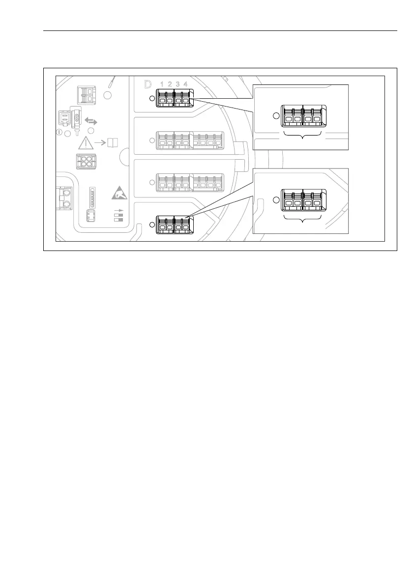
7.8.4 Modbus, V1 or WM550 output
D
E
F
C
B
A
1
1
1
1 3
2
2 4
1
HR
CDI
WP
on
SIM
2
2
3
3
4
4
1
1
2
2
3
3
4
4
5
5
6
6
7
7
8
8
POWER
A
1 2 3 4
A1-4
i
D
1
2 3 4
D1-4
A0031200
37 Possible locations of the Modbus or V1 modules (examples); depending on the device version these
modules may also be in slot B or C .
Depending on the order code the device may have one or two Modbus or V1 communication
interfaces. These are configured in the following submenus:
Modbus
Setup → Advanced setup → Communication → Modbus X1-4 →Configuration
V1
• Setup → Advanced setup → Communication → V1 X1-4 → Configuration
• Setup → Advanced setup → Communication → V1 X1-4 → V1 input selector
WM550
• Setup → Advanced setup → Communication → WM550 X1-4 → Configuration
• Setup → Advanced setup → Communication → WM550 X1-4 → WM550 input selector
 Loading...


