Prosonic Flow 92
12 Endress+Hauser
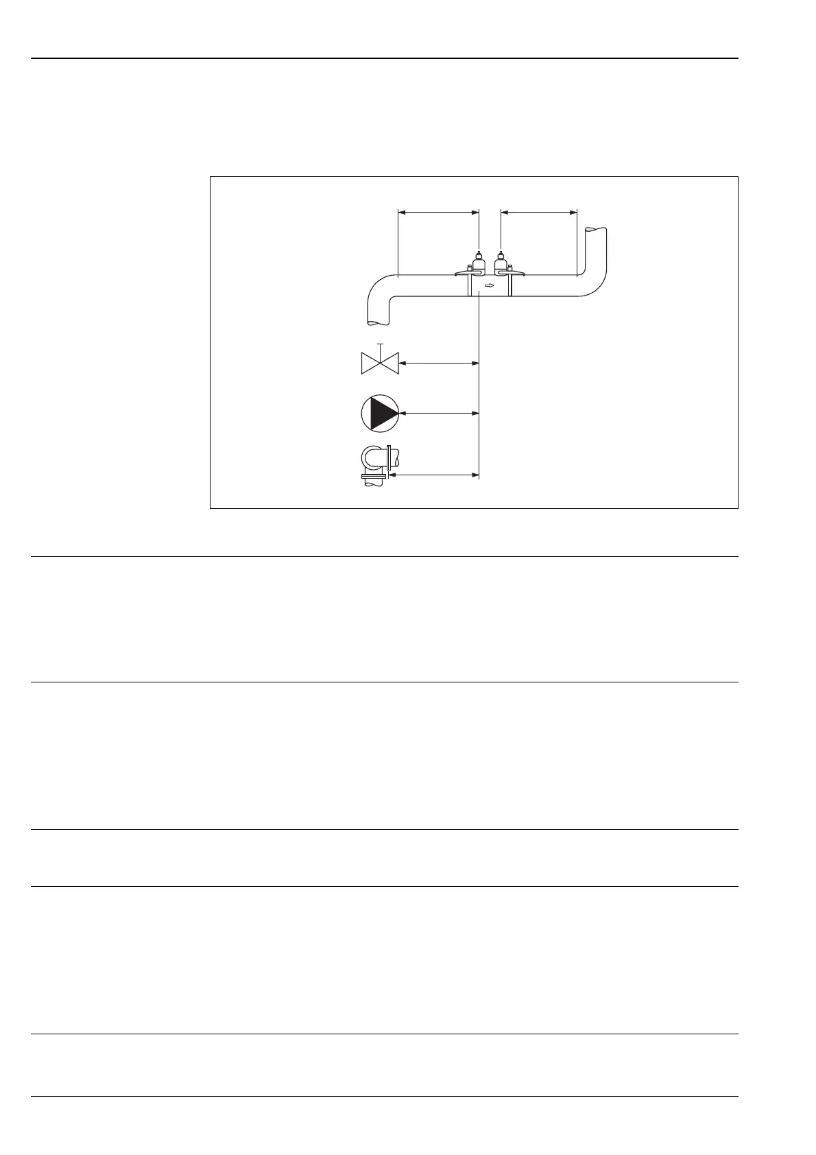
Inlet and outlet runs If possible, install the flow measuring sensors well clear of fittings such as valves, T-pieces,
elbows, etc. If several flow obstructions are installed, the longest inlet or outlet run must be con-
sidered. Compliance with the following requirements for the inlet and outlet runs is recommended
in order to ensure measuring accuracy.
1 = Valve, 2 = Pump, 3 = Two pipe bends in different directions
Connecting cable length Shielded cables are offered in the following lengths:
5 m and 10 m
In order to ensure measuring accuracy, comply with the following instructions during installation:
Route the cable well clear of electrical machines and switching elements.
Environment
Ambient temperature • Transmitter Prosonic Flow 92:
-10...+45 °C
• Flow measuring sensors Prosonic Flow W/U:
-20...+60 °C
• Sensor cable PVC -20...+70 °C
Avoid direct sunlight, particularly in warm climatic regions.
Storage temperature The storage temperature corresponds to the operating temperature range of the transmitter and
the appropriate flow measuring sensors and the corresponding sensor cable (see above).
Degree of protection • Transmitter Prosonic Flow 92:
IP 50
• Flow measuring sensors Prosonic Flow W:
– Sensorbody in IP 67 (NEMA 4X)
– BNC adapter in IP 52
• Flow measuring sensors Prosonic Flow U:
IP 52
Shock and vibration
resistance
According to IEC 68-2-6
≥ 15 x DN
≥ 40 x DN
≥ 20 x DN
≥ 40 x DN
≥ 5 x DN
1
2
3
F06-9xxxxxxx-11-05-00-xx-005
 Loading...


