TMT142 HART® Commissioning
29
4 Commissioning
4.1 Function check
Prior to commissioning, please ensure that:
• The device has been mounted correctly and
• the electrical connection is correct.
4.2 Switching on the measuring device
Once the final checks have been successfully completed, it is time to switch on the supply
voltage. The device is ready for operation after approx. 18 seconds!
Normal measuring mode commences as soon as the switch-on procedure is completed. A
measuring value and/or a status variable appear on the display.
4.3 Display and operating elements
4.3.1 Display
A0024547
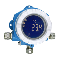
Fig. 5: LC display of the field transmitter (illuminated, can be plugged in in 90° steps)
Display symbols
Pos. no. Function Description
1 Bargraph display In 10% steps with overrange and underrange marks. The
bargraph display flashes when an error occurs.
2 Display ’Warning’ This display mode appears when an error occurs or a warning
is given.
3 Engineering unit display K, °F, °C or % Engineering unit for the measured value being displayed.

 Loading...


