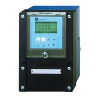
Do you have a question about the Endress+Hauser iTEMP HART TMT 182 and is the answer not in the manual?
Guidelines for appropriate and intended use of the transmitter.
Procedures for safe installation, setup, and operation.
Safety measures and requirements for operation.
Instructions for returning the unit for service or repair.
Explanation of safety symbols used in the manual.
How to identify the transmitter using legend plates.
Information specific to units certified for hazardous areas.
Details on CE marking and compliance with EU guidelines.
List of items included in the product package.
Environmental and site requirements for installation.
Physical dimensions of the head transmitter.
Specifies suitable locations for mounting the transmitter.
Information on acceptable mounting angles for the unit.
Step-by-step guide for mounting in a connection head.
Steps for installing the transmitter in a field housing.
General overview of wiring and terminal connections.
Connecting sensors, output signal, and HART.
Details on establishing HART communication.
Information on grounding and potential equalization.
Electrical connection for DXR 275.
Electrical connection for Commubox FXA 191.
Methods for communicating with the transmitter.
Using the DXR 275 for operation.
Using Commuwin II software for operation.
Checking installation and basic functions.
Streamlined setup for standard operation.
Configuring the transmitter using HART protocol.
Detailed explanation of transmitter functions.
Procedures for calibrating the transmitter's basic settings.
Using ReadWin® 2000 for configuration.
Using SMC32.exe for linearisation and matching.
List of compatible accessories and software.
General guidance for troubleshooting.
Explanation of fault codes and their meanings.
Troubleshooting without specific error messages.
Troubleshooting RTD connection issues.
Troubleshooting TC connection issues.
Information on available spare parts.
Guidelines for proper disposal of the unit.
Overview of operational principles and system setup.
Details on accepted input signal types and ranges.
Specifications for different input sensor types.
Technical specifications for thermocouple inputs.
Output signal characteristics and types.
Accuracy specifications for different sensor types.
Allowed operating temperatures.
Protection rating against dust and water.
Physical design and dimensions of the unit.
Overview of how the transmitter functions and is constructed.
Description of the system that transforms input signals.
| Brand | Endress+Hauser |
|---|---|
| Model | iTEMP HART TMT 182 |
| Category | Transmitter |
| Language | English |


