24 25
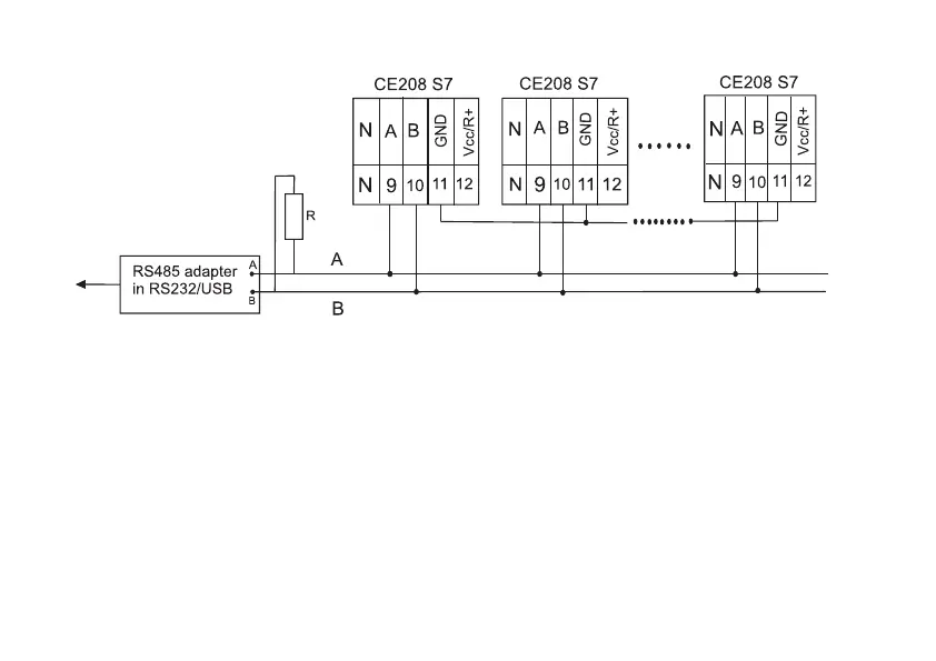
R – termination resistor with a rating equal to the cable wave impedance
Figure 3.3 – CE208 S7 meter connection diagram with an RS485 interface using an external adapter
RS485/RS232, RS485/USB to the PC
Note – Biasing resistors (+R) and (-R) (nominal 100 kΩ) are installed in the meter and are always connected
to the A and B lines, respectively. When it is necessary to connect external biasing resistors (resistance of 560 Ω),
you should: make contact between pin 9 and pin 12, in this case the +R resistor installed in the meter is activated;
between pins 10 and 11 install an external (-R) resistor with a resistance of 560 Ω. In order to avoid line overload,
activation of biasing resistors with a resistance of 560 Ω, as a rule, is only performed for the extreme meters.
3.4.2.3 To exchange data via the optical interface, an optical probe in accordance with GOST IEC 61107-2011
is used.
 Loading...