Do you have a question about the ENERMAX LIQTECH II and is the answer not in the manual?
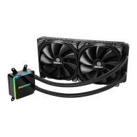
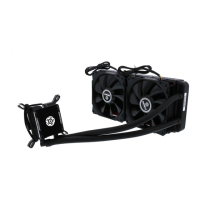
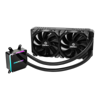
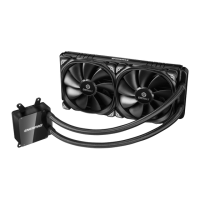
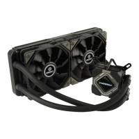
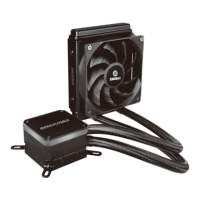
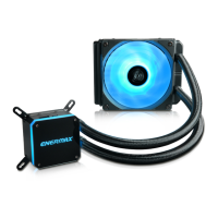
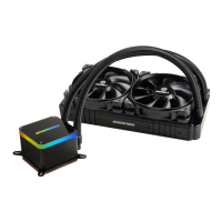
Attach the fan and the radiator to the chassis for installation.
Insert position screws into the back plate and fix them with washers.
Insert LGA1700 position screws into the back plate and fix them with washers.
Install the Intel back plate onto the motherboard using stand-offs.
Tighten the LGA 2011/2011-3/2066 screw to the motherboard.
Apply the thermal grease evenly on the CPU surface.
Remove the protective film from the cold-plate.
Place the pump on the CPU and tighten the spring screws.
Connect the pump power connector to the motherboard.
Connect the fan connector to the motherboard.
Attach the fan and the radiator to the chassis for installation.
Remove the preinstalled Intel clip and install the AMD clip to the pump.
Remove original screws and place the back plate back into position.
Tighten the AMD screw to the AMD stock back plate.
Apply the thermal grease evenly on the CPU surface.
Remove the protect film from the cold-plate.
Place the pump on the CPU and tighten the spring screws.
Connect the pump power connector to the motherboard.
Connect the fan connector to the motherboard.
Connect RGB Sync cable to adapter and motherboard for GIGABYTE boards.
Connect RGB Sync cable, power connectors, and SATA power cable.
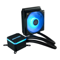
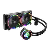
Explains LED colors for modes: Light Effect, Effect Speed, Brightness, Auto-run.
Controls effect speed using M, ▲, and ▼ buttons.
Adjusts brightness using M, ▲, and ▼ buttons.
Runs all 10 pre-set light effects in a loop.
| Radiator Material | Aluminum |
|---|---|
| Radiator Dimensions (360 model) | 394 x 120 x 27 mm |
| Fan Dimensions | 120 x 120 x 25 mm |
| Connector | 4-Pin PWM |
| Warranty | 5 years |
| Radiator Size | 360 |
| Socket Compatibility | AMD AM4/AM3+/AM3/AM2+/AM2/FM2+/FM2/FM1 |