Page 20 www.enersys.com Publication No. US-RE-IOM-002 January 2012
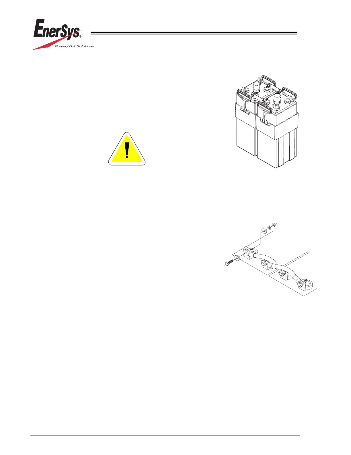
4. Lift the next cell/battery to be installed and place it next to
the previously installed unit. See Figure 7.1. Be certain to
allow proper spacing between cells/jars as outlined in
Section 7.2.2. Observe proper polarity orientation.
5. Repeat Procedures 5 thru 7 until all units are installed.
See Figure 7.2.
Do NOT use any kind of tool to pry cells into
position.
6. As soon as cells are unpacked and installed in position,
remove the shipping vent plugs and immediately install
the flame arrestors. DO NOT attempt to charge cells
unless flame arrestors are in place.
Once installed, DO NOT REMOVE the flame arrestors.
They are provided with a filling funnel for adding water.
Add water to the cells immediately after the indicator falls
to the low level. Do not permit the electrolyte level to
drop below the bottom of the tube on the flame arrestor.
Allowing too low a level defeats the flame arrestor
function.
7. Number the cells starting from the positive terminal of the
battery for maintenance purposes. Pressure-sensitive
adhesive labels are available from EnerSys
®
. Before
applying the cell numbers, clean surfaces according to
Procedure 3 in Section 12.1.1.
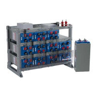
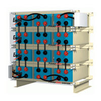
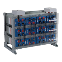
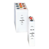
MULTI CELL UNITS (6RE)
CONNECTIONS
Figure 7.2
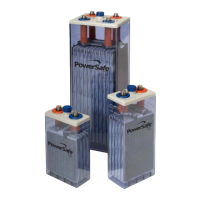
SINGLE CELL (1RE)
CONNECTIONS
Figure 7.1