ENFORCER Voice Dialer
SECO-LARM U.S.A., Inc. 5
Installing the Voice Dialer, continued:
1. Select a location for the dialer near a standard electrical outlet (if user-supplied 12VDC
adapter is to be used), a telephone wall jack, and the alarm control panel, but out of sight. The
dialer should not be exposed to direct sunlight or rain, and must not be mounted near heat
sources such as radiators, heating ducts, or stoves.
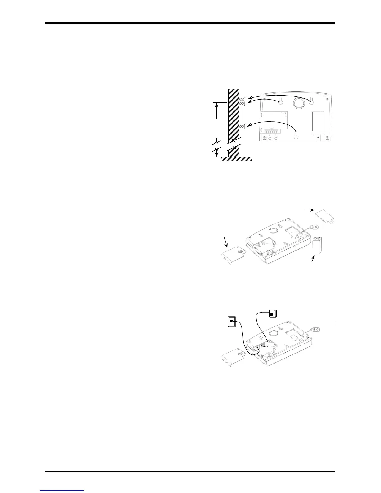
2. For wall-mount, use the wall mounting template to
drill holes and attach 3 screws into the wall at the
desired location. For convenience, 5~6ft (1.5~2m)
above the floor is recommended (Fig. 1).
3. Remove the cable cover and battery cover from
the back of the voice dialer (Fig. 2).
4. Install a 9VDC backup battery (not included).
Reattach the battery cover.
5. Connect the dialer to up to three detectors or
groups of detectors in series using the connection
terminals as shown in the wiring diagram (see pg.
3). The dialer can also be connected to three
separate alarm control panel outputs of a separate
alarm system. When Trigger 3 is used, the jumper
connection to ground must be removed.
6. Power:
a. If the dialer is to be powered from the alarm
control panel, connect the alarm power outputs
to the DC Plug-to-terminal block (included) and
plug into the dialer’s DC power jack (see pg. 3).
b. If using a 12VDC adapter (not included), plug
the adapter into the dialer’s DC power jack.
7. Connect one end of the included telephone cable to
an existing Touch-Tone line wall socket, and the
other end to the dialer’s “LINE” jack. The wall socket
line must be connected to the dialer’s “LINE” jack for
proper operation. Optionally, connect an extension telephone using the telephone’s cable (not
included) to the “TEL” jack (Fig. 3). Reattach the cable cover.
8. If an external alarm is desired, connect according to the wiring diagram (see pg. 3).
9. For wall installation, place the unit over the heads of the screws installed in step 2 (Fig. 1) and
slide down. Check that the unit is firmly attached and tighten or loosen the screws as needed.
10. Once all connections are made, the dialer is ready to be programmed.
Fig. 3
Fig. 1
5~6ft
(1.5~2m)
9VDC Battery
(not included)
Fig. 2
Cable
Cover
Battery
Cover
 Loading...