ENFORCER Voice Dialer
SECO-LARM U.S.A., Inc. 3
Operating voltage
10~18 VDC
Current draw (max.)
Alarm message length (user recorded)
message + 6s individual message for each input
Programmable alarm phone numbers
Maximum digits per phone number
Programmable dial attempts
1~2 times for each number
Trigger inputs
Programmable high (input >3.5V, max. 15V) N.O. or N.C.
or low (input <1V) N.O. or N.C.
2A@24VDC, NO/NC, programmable 1~255s
Dimensions
4
1
/
16
"x5
9
/
16
"x1
11
/
16
" (104x142x43 mm)
*
The E-922CPQ may work with some digital phone systems (single-line or PBX), depending on the system.
Specifications:
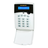
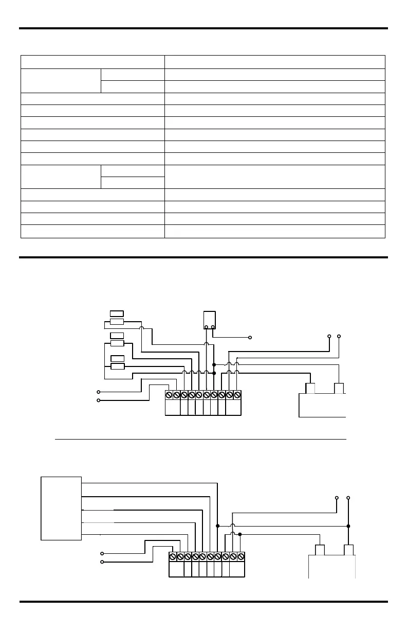
Sample Applications and Wiring Diagrams:
To telephone line
Auxiliary controlled device
(gate/door, siren, strobe, etc.)
Contact/sensor or group of
contacts/sensors (L-NO)
Contact/sensor or group of
contacts/sensors (H-NO)
Contact/sensor or group of
contacts/sensors (L-
Stand-alone installation
or button
10~18 VDC
+
–
To trigger relay
(on/off)
Auxiliary controlled device
(gate/door, siren, strobe, etc.)
10~18 VDC
–
To telephone line
Alarm system installation
Alarm
System
NOTE: If the "Inhibit" input is not used, it should be programed as low N.C. (L-NC, see Setting the Trigger Level, pg. 7).
RELAY
TEL
RELAY
TEL
 Loading...