ENFORCER Voice Dialer
4 SECO-LARM U.S.A., Inc.
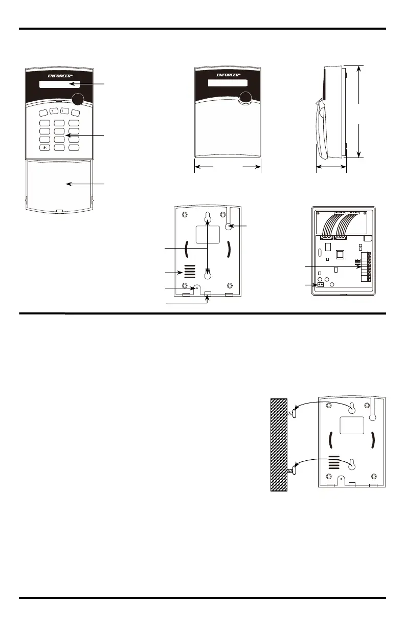
Overview:
1. Select a location for the dialer. The dialer should not be exposed to direct sunlight or rain, and
must not be mounted near heat sources such as radiators, heating ducts, or stoves.
2. Loosen the attachment screw on the lower end of the dialer (see Overview, pg. 4) and remove
the back. For countertop installation, skip to step 4.
3. For wall mount, and use the back as a template to mark
mounting holes and wiring hole. Drill holes and attach 2
screws into the wall at the desired location. For convenience,
5~6ft (1.5~2m) above the floor is recommended (Fig. 1).
4. Run wires for the telephone connection, for power, from the
auxiliary output, and from up to three sensors/contacts or
groups of sensors/contacts connected in series referring to
the wiring diagram (see Sample Applications and Wiring Diagrams, pg. 3). Alternatively, the
dialer can be connected to three separate alarm control panel outputs.
5. Thread all wires through the wiring hole, place the back over the heads of the screws installed
in step 2 (Fig. 1), and slide down. Tighten or loosen the screws as needed.
6. Connect all wires to the terminal block, again referring to the wiring diagram (see pg. 3) and
attach the dialer unit to its back, tightening the attachment screw to hold it firmly into place.
TE L
P1
P2
P3
IN
C NC
+1 2
REL AY
1
2 3
4 5 6
7 8 9
0 #
E
S
C
E
N
T
E
R
U
P
D
O
W
N
Wiring hole
and cutout
Keypad cover
Front (keypad cover open)
Front (cover closed)
Side
Back
Back (base removed)
Auto Dialer
Ready
Auto Dialer
Ready
Terminal block
Speaker connector
Keypad
5
9
/
16
"
(142mm)
11
16
4
1
/
16
"
(104mm)
Microphone
LCD Display
Installation:
Fig. 1

 Loading...