Page 6
Omniguard™ 4 Owner’s Manual
Page 7
Engineering Solutions Inc
6. Use ▲/▼ to adjust the value of the ALARM 2 setting.
7. Save the updated settings for both Alarm 1 & 2 by pressing SAVE.
Saved settings are printed and logged into memory.
or press EXIT to return to Main Menu without saving.
Note: Press HELP at any time to view more
detailed help information.
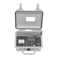
Hanging the Omniguard 4
The Omniguard 4 can be hung on a wall for easy viewing and to
keep it off of the floor, away from possible damage. Hanging the
Omniguard 4 by the clip allows the cover to close, protecting the unit
from water damage while allowing the LCD display and STATUS
LED to be viewed through the window on the cover. The hose and
AC cord should exit the case thru the foam slot, then the cover should
be latched closed to protect the unit from damage.
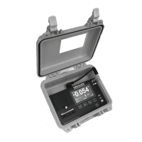
Use the DISPLAY key to flip the display orientation when hanging the
unit by its handle (see below).
Caution: Only hang the Omniguard 4 on a sturdy
surface. A fall could damage the unit and disrupt
accurate pressure measurements.
Display Modes
The DISPLAY key on the Omniguard 4 is used to vary the display
view and orientation to accommodate hanging the unit by its handle.
The pressure reading can be enlarged to enhance viewing from
across the room.
Press DISPLAY to toggle the views in the sequence shown below.
Section 3: Quick Setup & Usage
This section is a quick reference for using your Omniguard 4.
1. Insert one end of pressure tubing inside the containment area.
Connect the other end of tubing to INLET 1.
2. Locate a safe place for the Omniguard 4 outside the containment
area. Plug the power cord into a power outlet.
3. Press the POWER ON/OFF key to turn the unit on. Set the correct
Time & Date if prompted. (This happens if the internal battery
has died and the built-in clock lost its settings. Don’t worry, the
battery is rechargeable and lasts an average of 30 days.)
4. If you want a printed copy of the previous job log, press the PRINT
JOB key.
5. Press START JOB to begin a new job. Enter a name for the new
job and then press SAVE. The previous job will end and its Job
Summary Report will print.
6. Check Alarm 1 & 2 setpoints (displayed in the monitor screen
window), adjust if needed.
The status bar will indicate WAITING FOR PRESSURE and the
STATUS LED will flash green until containment pressure reaches the
operating window. Once reached, the status bar will display NORMAL
and the STATUS LED will change to steady green indicating that
the unit is now in its normal operational mode. Printing and logging
of pressure readings begin once the normal operational mode is
achieved.
During normal operation, the highest and lowest pressure readings
will be printed and logged into memory with a time/date stamp every
15 minutes (the default Print/Log rate).
If the monitored pressure then goes outside the operating window,
the unit will go into alarm mode. The buzzer will sound, the status
bar will change to a flashing >>ALARM<< and the STATUS LED will
flash red. The print and log rate of the pressure readings will increase
to every 15 seconds (the default Print/Log Alarm rate).
To turn the alarm off press the ALARM SILENCE key.
Sample Session: Viewing/Changing Settings
1. From the Monitor Screen, press MENU to go to the Main Menu.
2. Use the ▲/▼ arrow keys to highlight ALARM SETPOINTS.
3. Press SELECT to go to the View Setting Screen and allow changes
to the ALARM SETPOINTS.
4. The ALARM 1 setting can now be increased or decreased by
using ▲/▼.
5. Once the desired value has been reached, press 3/4 to
highlight ALARM 2 setting.
press DISPLAY
"WC
-0.038
"WC
-0.038
press DISPLAY
press
DISPLAY
press
DISPLAY
 Loading...