Page 8
Omniguard™ 4 Owner’s Manual
Page 9
Engineering Solutions Inc
Loading the Thermal Printer Paper
Caution: Only use Omniguard thermal printer
paper! Thermal paper prints on only one side, the
side away from the paper roll. If the roll is installed
incorrectly the printer will be able to advance the
paper but be unable to print on it.
C
B
A
B
C
A
1. Remove the printer housing lid
with the thumbscrew. Cut the
end of the paper to a tapered
point.
2. Place the paper roll, marked A,
into the tray so the paper unrolls
from the bottom.
3. Insert tapered point into slot
marked B, feed through until
tapered point can be pulled from
the top at slot marked C.
Do not use the PAPER FEED key
to advance the paper.
4. From C, gently pull until the
tapered portion is completely
exposed.
5. Replace lid onto the paper
housing and secure with the
thumbscrew.
Section 4: Detailed Operation
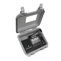
The Omniguard 4 monitors and records the differential pressure
between INLET 1 and INLET 2 (Reference).
In abatement applications the Omniguard 4 should be located outside
the containment area and not in any antechambers (i.e. shower or
changing room). This allows a supervisor or hygienist to monitor
pressure readings without entering the containment area.
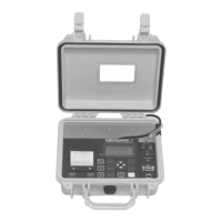
Work Area Setup (see Appendix C for more details)
The Omniguard 4 should be placed on a solid (non-vibrating) surface,
excessive vibrations disrupt accurate pressure measurement.
1. The intake end of the pressure tubing must be located a minimum
of 5 feet away from any openings or HEPA fan/filter units.
Choose a location away from excessive dust or moisture.
2. Cut a 1/2” slit in the polyethylene barrier and feed approximately
1 ft. of pressure tubing through it. Tape the tubing securely to the
polyethylene.
3. Connect the free end of the tubing securely over INLET 1. Be
careful not to turn the nozzle.
4. Route the hose and AC cord through the foam notch area on the
upper right corner of the case. Close the lid (being careful to not
pinch the hose or AC cord) to protect the unit from damage.
5. The maximum hose length is limited to 70 ft (for 3/16”ID hose).
Lengths beyond 70 ft can degrade reading accuracy.
6. Program the Job Name and confirm the Alarm settings are correct.
The Alarm 1 and Alarm 2 settings should be in negative units
when used to monitor a negative (vacuum) containment area. For
positive containment applications, use positive units (Inches WC,
Millimeters WC or Pascals) for the Alarm settings.
NOTE: It is important that there be no kinks or
sharp bends in any part of the tubing. Any blockage
could inhibit accurate recording of the pressure in
the containment area.
Power-Up
To begin operating the Omniguard 4, plug the power cord into a
standard wall outlet supplying 115VAC, 60Hz and press the POWER
ON/OFF key. The first time a new unit is turned on the settings will
be at default values.
Initial Power-Up
Set the Date & Time and Alarm 1 & 2 setpoints because they are
set at the factory defaults. The Date & Time will only need to
be set once. The Alarm 1 & 2 setpoints will need to be adjusted
for each job’s requirements.
 Loading...