EasyManua.ls Logo

Enovation Controls Murphy PowerCore MPC-10 - User Manual

Enovation Controls Murphy PowerCore MPC-10
65 pages
Print Icon
To Next Page IconTo Next Page
Loading...
Software Release: [App: 02.09.10051.00; Config: 2.9.20024; Built in PowerVision Configuration Studio Version: 2.9.23042;
BTL: 02.09.10015.00]
00-02-0939
2019-06-13
Section 40
PowerCore
®
MPC-10 Engine Controller &
TEC-10 Panel
Operations Manual
To see this manual in Spanish, German, French or Italian, please go to
support.enovationcontrols.com,
then search for MPC-10 or TEC-10.
In order to consistently bring you the highest quality, full-featured products, we reserve the right to change our
specifications and designs at any time.

Table of Contents

Question and Answer IconNeed help?

Do you have a question about the Enovation Controls Murphy PowerCore MPC-10 and is the answer not in the manual?

Enovation Controls Murphy PowerCore MPC-10 Specifications

General IconGeneral
Input Voltage8-32 VDC
Microprocessor32-bit
Memory512 KB Flash, 64 KB RAM
Display TypeLCD
Communication ProtocolsRS485
Operating Temperature-40°C to +70°C
InputsAnalog, Digital, Frequency
OutputsDigital
CertificationsCE, UL

Summary

Warranty Information

General Safety Warnings

Specific Warning: Automatic Start

Lens Cleaning Procedures

Introduction to the MPC-10;TEC-10

Murphy PowerCore 10 Overview

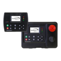
Details the Murphy PowerCore 10 controller's features, capabilities, and intended applications.

Engine Application States and Delays

Explains the sequence of machine states and associated delays during auto operation.

User Interface Overview

Operator Controls and Button Functions

Describes the function of each button on the MPC-10 / TEC-10 control panel.

Accessing the Menu System

Main Menu Structure

System Settings

Covers date/time, units, language, brightness, and service reminders.

Engine Settings

Details user-configurable parameters for engine setup, including type and speed source.

Advanced Engine Settings

Covers less common parameters like J1939 address, ECU source, and crank settings.

Throttle Menu

Input; Output Configuration

Application Configuration

Pump All Purpose Application

Details auto start and throttle methods for pump applications.

Air Compressor Application

Details auto start and throttle methods for air compressor applications.

Hose Reel Irrigation Application

Frost Protection Application

Chipper Application

Start;Stop Timers

Communication Settings

Passcodes Management

Load Configuration

Auto Start;Stop Functions Defined

Single Contact Start;Stop

Occurs when a remote contact is active for auto start and inactive for auto stop.

Two Contact Maintained Start;Stop

Occurs when both remote contacts are active for auto start and inactive for auto stop.

Transducer Start;Stop Functions

Utilizes pressure, level, or temperature transducers for auto start/stop.

Local Start Key Start;Stop

Uses the green and red buttons on the interface for auto start and stop.

Quick-Start Setup Guide

Mechanical Engine Setup

Step-by-step configuration for mechanical engine parameters.

J1939 Electronic Engine Setup

Setting to Auto Start on Single Contact Input

Setting to Auto Start on Local Start Key

Setting up Auto Start;Stop for 2 Contact Inputs

Setting to Auto Start on Pressure

Setting up Auto Start on Level

Setting to Auto Start on Clock

Setting to Auto Start on Temperature

Setting up to Stop Engine with Countdown Timer

Screen Examples

Additional Screens

Application Screen Display

Regeneration Mode Screens

System Information Display

Digital Output Status

Relay Status

Digital Input Status

Analog Input Status

Service Life Remaining Screens

ISO Icons Reference

Icon Troubleshooting

Menu Glossary: System Settings

Menu Glossary: Engine Settings

Menu Glossary: Advanced Engine Settings

Menu Glossary: Throttle Menu

Menu Glossary: Input; Output Menu

Menu Glossary: Application Configuration

Menu Glossary: Start; Stop Timers

Menu Glossary: Communication

Menu Glossary: Passcodes

Menu Glossary: Load Configuration

Communication Mapping

RS485 Modbus Registers

Details the MPC-10 & TEC-10 RS485 Modbus register map for communication.

CAN Parameter Map

Supplementary Information

Passcodes Explained

Describes the three levels of passcode protection and their management.

PC Configuration Software

Information on using PowerVision for Controllers software for configuration.

MPC-10 Specifications

TEC-10 Specifications

Related product manuals