Mount the IQ Battery(ies) on the wall
* WARNING: Risk of injury. Take care when lifting.
Each IQ Battery base unit is heavy (40.5 kg/ 89.3 lbs) and requires
two persons to lift.
* WARNING! Risk of injury and equipment damage. Avoid dropping
the IQ Battery(ies). Doing so may create a hazard, cause serious injury,
and/or damage the equipment.
* WARNING! Risk of injury and equipment damage. Protect the IQ
Battery(ies) from impact damage and improper use.
* WARNING! Risk of injury and equipment damage. Do not hold the
microinverters to lift the unit during installation.
A ) Two person together must lift a single IQ Battery base unit from the
packaging and place it in upright position (as shown in the following
image) on a at surface.
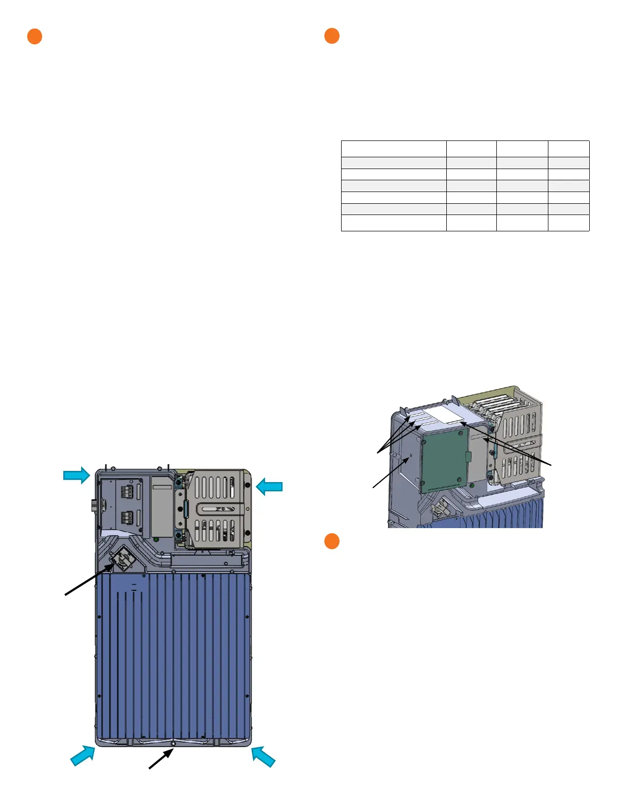
B ) Locate the IQ Battery lifting points:
C ) The rst person lifting must use points a and d (as shown) to lift the
battery.
D ) The second person lifting must use points b and c (as shown) to lift
the battery.
E ) Together, lift the IQ Battery and bring it to the already mounted
bracket.
F ) Hold the IQ Battery straight so that the four bolts on the back of the
IQ Battery pass through the four key hole slots on the corner of the
mounting bracket.
* WARNING! Risk of injury and equipment damage. Do not release
the IQ Battery unit until you ensure that the IQ Battery unit is fully
seated in the wall-mount bracket shelf.
G ) Once all four battery bolts fully pass through the mounting bracket
key hole slots, lower the battery down until fully seated within the
wall-mount bracket and set into the bottoms of the key holes.
H ) Attach the battery to the mounting bracket aligning the screw hole
at the bottom of the battery with the screw hole at the bottom of the
bracket. Tighten the bottom screw to 8Nm (70.8 lb-in).
I ) To record the installation of each IQ Battery base unit, scan the serial
number label using Enphase Installer App and your mobile device.
5
Bottom screw hole
DC Switch
d
c
a b
Prepare for eld wiring
+
DANGER! Risk of electric shock. The DC switch must be in the
Locked position before performing this step.
A ) Drill the left wall of eld wiring compartment to accommodate the conduit.
B ) Connect eld wiring to the top three terminal blocks.
C ) Size the conductors (Lines and Ground) to account for voltage rise and
to conform to the tables below. Design for a voltage rise total of less
than 2%. IQ Battery can use any circuit breaker size between 10 A and
40 A. Breaker rating and wire size are installation dependent.
Number of
IQ3T/IQ10T units
Current (A) Minimum wire
size (AWG)
Breaker
rating (A)
1*IQ3T 5.3 14 10
2*IQ3T 10.7 14 15
3*IQ3T or 1*IQ10T 16.0 12 20
4*IQ3T or (1*IQ10T + 1*IQ3T) 21.3 10 30
5*IQ3T or (1*IQ10T + 2*IQ3T) 27.7 8 35
6*IQ3T or 2*IQ10T or
(1*IQ10T + 3*IQ3T)
32.0 8 40
*IQ3T refers to IQ Battery 3T
*IQ10T refers to IQ Battery 10T
In all cases in the table, it is possible to always use larger conductors
and a breaker sized for that conductor or smaller. For Example in row 3,
with 3*IQ3T or 1*IQ10T, it is possible to use:
a) 12 AWG wire with 20 A breaker, or
b) 10 AWG wire with 20 A or 30 A breaker, or
c) 8 AWG wire with 30, 35, or 40 A breaker
+ DANGER! Risk of electric shock. Check that the dedicated circuit
breaker protecting the branch where the IQ Battery(ies) will be
connected is turned off before wiring.
* WARNING! Risk of equipment damage. The DC switch must be
OFF before installing, otherwise IQ Battery will try to form a grid.
6
Location for
conduit cut out
Finished Goods
Serial numbers
labels
Install conduit and eld wiring
+
DANGER! Risk of electric shock. The DC switch must be in the
locked position before performing this step.
A ) If installing an IQ Battery 10T, install the interconnect cable assembly.
•
Face the front of the batteries, and insert the interconnect cable
assembly through the front cable slot from within the eld wiring
compartment, with the arm of the interconnect cable pointing up,
making a “U” shape.
B ) Using the conductors and suitable conduits, connect the AC disconnect
and the rst adjacent IQ Battery. Use the conduit openings provided to
connect the conduit and pass the wires through them. Note that if an
Enphase IQ System Controller is in line-of-sight, the breaker can service
as a disconnect.
* WARNING! Risk of equipment damage. Do not modify or rewire the
pre-installed wiring or bonding connections in the eld wiring compart-
ment.
* WARNING! Risk of equipment damage. Always connect to two
Lines (active) and one ground.
(CONTINUED ON NEXT PAGE)
7
PCBA Serial
Numbers

 Loading...


