Install conduit and eld wiring (continued)
C ) Connect each wire in the eld wiring compartment to its corresponding
conductor (Lines and Ground). Each terminal accepts two 14-8 AWG
conductors (11mm/7/16 inch strip length). Tighten to 1.6 Nm (14 lb-in).
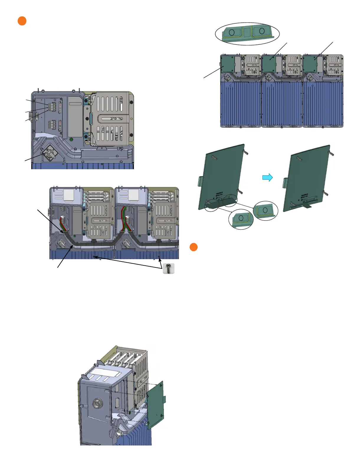
D ) If installing an IQ Battery 10T, secure the inter-connection cable assem-
bly between the IQ Battery units. You must connect the interconnect
cable to the bottom three terminal blocks for the left unit and top three
terminal blocks for the right unit.
* WARNING! Risk of equipment damage. Do not daisy chain more than
six total IQ Battery 3T or two IQ Battery 10T on a single branch circuit.
7
+
DANGER! Risk
of electric shock. The
system is not ready
to be energized! Do
not close the circuit
breaker or turn on the
DC switch.
2
3
1
4
1. Terminal for L1 in
from conduit
opening
2. Terminal for L2
in from conduit
opening
3. Terminal for
ground in from
conduit opening
4. DC Switch
Interconnect
cable
Ensure that the
interconnect
cable is properly
seated in the
slot.
Assemble using two
M4 screws from the
c o v e r a c c e s s o r i e s k i t :
Tighten to 1.9Nm/16.8 lb-in.
E ) After all wires in the eld wiring compartment are connected and
secured, check that there are no exposed conductors.
F ) If connecting additional IQ Batteries, use another conduit and another
set of wires to connect between eld wiring compartments.
G ) Gently arrange all the wires and connectors inside the eld wiring
compartment.
H ) Secure the eld wiring compartment cover. Use a cross-head screw
driver to tighten the cover screws to 2.3Nm (20.3 Ib-in).
I ) Break tab 1, tab 2,
or both tabs on the
eld wiring door
along the yellow
lines indicated for
interconnect cable
entry as shown.
J ) Do not break tabs
when installing the
IQ Battery 3T.
Cover and energize the system
* WARNING: Before energizing, make sure that ALL IQ Batteries in
the system are properly installed and conductors terminated.
* WARNING! Risk of equipment damage. Ensure that no wires are
pinched before replacing the cover.
NOTE: Check the box for updates on cover installation instructions.
IMPORTANT: The section 8 and 9 will depict instructions for assemby
and disassembly of IQ Battery 3T cover, simillar instructions are appli-
cable for IQ Battery 10T cover.
A ) Check that the eld wiring compartment cover(s) for all IQ Batteries in
the system are closed and secured.
* WARNING: Complete the Enphase IQ System Controller and En-
phase Combiner installations before turning the DC switch(es) ON.
+ DANGER: Risk of electric shock. Before continuing, check that
IQ Battery units are properly wired, and ground connection does not
have a L1 or L2 connection, as this introduces a safety hazard.
• Apply AC power to the IQ Battery circuits. Do NOT turn on the IQ Battery
DC switch(es).
• Using a voltmeter measure the IQ Battery chassis metal to ground (e.g.,
grounded conduit) and ensure there is no AC voltage source present. If
wiring is incorrect, a ground fault may exist, and the AC voltage may read
~120VAC. If voltage is present, DO NOT touch the chassis, and immediately
remove AC power from the IQ Battery circuits.
• Remove AC power to the IQ Battery circuits and correct the wiring.
+ WARNING! Risk of electric shock and equipment damage. If the
DC switch is ON, AC voltage might be present at the terminals.
+ DANGER: Risk of electric shock. AC voltage might be present
at the output when the DC switch is on.
* WARNING: Branch Circuit protection for IQ Battery MUST
be ON (with AC voltage present) before turning DC switch ON.
Wait for 15 seconds after turning branch circuit protection ON and
check that LED on IQ Battery is ON (Any color LED is ON) before
turning DC switch ON.
8
1
2
Tab 1 and 2 to
be broken
Tab 2 to be
broken
Tab 1 to be
broken
 Loading...


