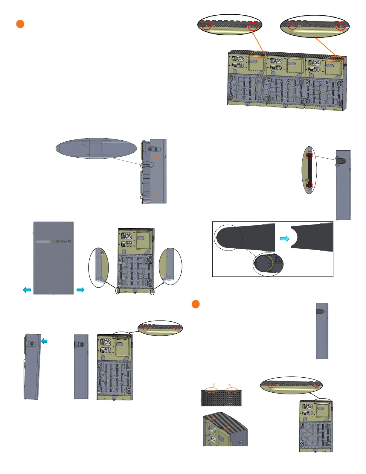
C ) Slide the IQ Battery cover in the indicated direction so that the hook of
the cover in the highlighted region goes into the slot provided for it in the
main unit (both sides of the main unit).
D ) Pull out the lower edges while sliding in the
cover and ensure that the tabs are locked to the back
plate as shown below before releasing.
E ) Once the cover reaches the position as shown in the side view image.
push the top portion of the cover and make sure that the cover is
locked in place, in the indicated regions.
8
Before pushing
into place:
Locked into
place:
F ) After assembling the IQ Battery cover, remove the break-out tab from
the conduit cover and assemble with the ribs
snapping in as shown:
G ) Break the conduit cover tab along the yellow
line as indicated before assembling to the main
unit:
9
Disassembly of the IQ Battery Cover
A ) Remove the conduit cover from the IQ Battery cover.
B ) Using the hand access slots pull the top plastic grill slightly in the
direction shown below (in order to unlock the top plastic cover from the
ribs highlighted in red.):
IQ Battery 10T Cover
IQ Battery 3T Cover
IQ Battery 3T Cover
Hand Access slots
NOTE: Only for reference purpose, the Enchage 10T Cover image is
shown above for locking.
Cover and energize the system (continued)
B ) Turn ON the AC power rst (branch circuit protection) and then turn
ON the DC switches of the IQ Batteries.
NOTE: Do NOT leave the IQ Battery unit’s DC switch in the ON position for
any extended period of time (such as overnight or for more than 24 hours)
unless IQ Battery is commissioned (communicating with IQ Gateway),
connected to AC, and has passed functional testing and is operational.
Leaving the DC switch ON without AC connection and communication with
the system will drain the battery and may cause damage to the battery
cells such that they no longer be able to charge. Damage resulting from
this improper installation and misuse is not covered under the product’s
limited warranty.
 Loading...


