Introduction
1-4
1
Power Supply Receptacles
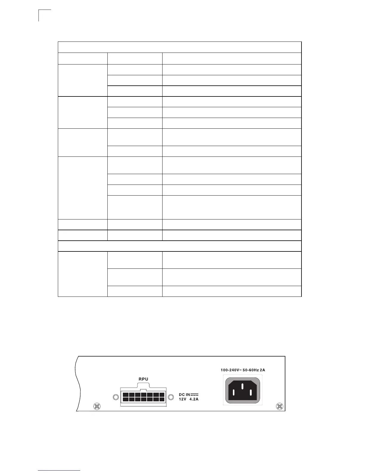
There are two power receptacles on the rear panel of the switch. The standard
power receptacle is for the AC power cord. The receptacle labeled “RPU” is for the
optional Redundant Power Unit (RPU).
Figure 1-4. Power Supply Receptacles
Table 1-2. System Status LEDs
LED Condition Status
PWR On Green The unit’s internal power supply is operating normally.
On Amber The unit’s internal power supply has failed.
Off The unit has no power connected.
Diag On Green The system diagnostic test has completed successfully.
Flashing Green The system diagnostic test is in progress.
On Amber The system diagnostic test has detected a fault.
RPU Green Lights steady to indicate that a redundant power unit is
attached and is in backup or active mode.
Off There is no redundant power unit currently attached.
Stack Flashing Amber An initial state of stacking configuration upon powering
on.
Green This switch is acting as the master unit in the stack.
Amber This switch is acting as a slave unit in the stack.
Flashing Green Indicates that the unit ID of each switch in the stack is
being displayed by port LEDs 1 to 8 (initiated by a CLI
command).
Link N/A This indicator is not currently implemented.
Duplex N/A This indicator is not currently implemented.
Module Ports
Port 25~26
(Link/Activity)
On/Flashing Amber Port has established a valid 10/100 Mbps network
connection. Flashing indicates activity.
On/Flashing Green Port has established a valid 1000 Mbps network
connection. Flashing indicates activity.
Off There is no valid link on the port.

 Loading...


