Connecting Switches in a Stack
3-7
3
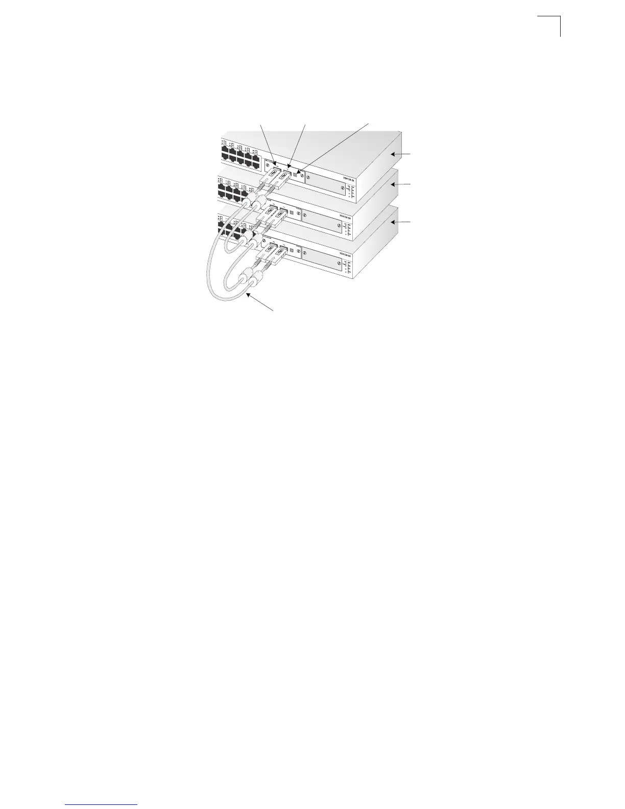
4. Complete the stack connections by plugging one end of a stack cable into the
TX port on the bottom unit and the other end into the RX port on the top unit.
Figure 3-7. Connecting Switches in a Stack
5. Select the Master unit in the stack by pressing the push button in on only one of
the stacking modules. Only one switch in the stack can operate as the Master,
all other units operate in slave mode. If more than one switch in the stack is
selected as Master, or if no switches are selected, the stack will not function.
Note: The stacking feature requires that all stacking module ports be connected and the
switches powered on. If one stack link is not connected, or if a switch is powered
off, the stack will not function.
Note: If the stacking connection is broken, the switches will become multiple standalone
switches.
Top-to-bottom connection
Transmit
Receive
Stack Master
Slave
Slave
Button pressed in
for Master mode
25
26
26
25
2
6
26
25
26
26

 Loading...


