JOHNSON CONTROLS
10
FORM ET130.13-NOM3 (708)
Series Flow ECM Motor Balancing
Fan must be energized prior to intro-
duction of air through the primary
air valve or the possibility exists that
the fan wheel will operate backward
(counter rotation). Reverse / counter
rotation of the blower over a period of
time will damage the ECM motor.
See Figure 2 for ETPWM Board Layout.
Commissioning
1. If remote balancing dampers are present set them
to full open.
2. Make sure there are no obstructions in the discharge
ductwork and/or at the plenum opening. If the unit
has a radiated sound damper at the plenum opening,
make sure it swings freely.
3. With unit de-energized, disable fan by disconnect-
ing one of the wires leading to fan relay coil or
contacts.
4. Energize unit.
5. Verify that there is 22 to 28 VAC across terminals
15 and 16 of ETPWM board.
6. Verify that there is 15 VDC across terminals G (+)
and COM (-) of ETPWM board.
7. Connect voltmeter to wire loop VDC (+) and wire
loop COM (-) of ETPWM board. Verify DC volt-
age is between 5.1 and 9.9 VDC.
8. De-energize unit and reconnect wire to fan relay
removed in step 3. Make sure that all wires are
reconnected per electrical schematic shipped with
unit.
9. Energize unit and let motor operate for a minimum
of 15 minutes. During this run-in, check ductwork
for any leaks and repair as necessary.
Balancing
1. Adjust fan to the design CFM using either the
Manual or Remote Fan CFM Adjustment method
listed below.
2. Attach a manometer or magnehelic to the differen-
tial pressure ports in the pneumatic tubing leading
to the high and low side of the inlet air probe and
measure the velocity pressure. Adjust and set the
primary maximum airfl ow as necessary to meet
job site requirements. See Table 2, Airfl ow vs.
Velocity Pressure chart. This chart, with different
inlet sizes, is also located on the side of the equip-
ment.
3. If balancing dampers are present, adjust and set
proportionally to desired position. To minimize
noise levels, and prevent premature ECM motor
failure, leave these dampers in the most open posi-
tion possible.
4. The maximum primary air balance may be checked
using the optional radiated sound damper, or by
suspending a sheet of notebook paper over the
inlet using a small psiece of tape. If the damper or
notebook paper is blowing out of the unit, the pri-
mary maximum airfl ow is too high. If the paper or
damper is being pulled into the unit, the maximum
primary airfl ow is too low. Optimum balance is
achieved when the damper or paper hangs straight
down.
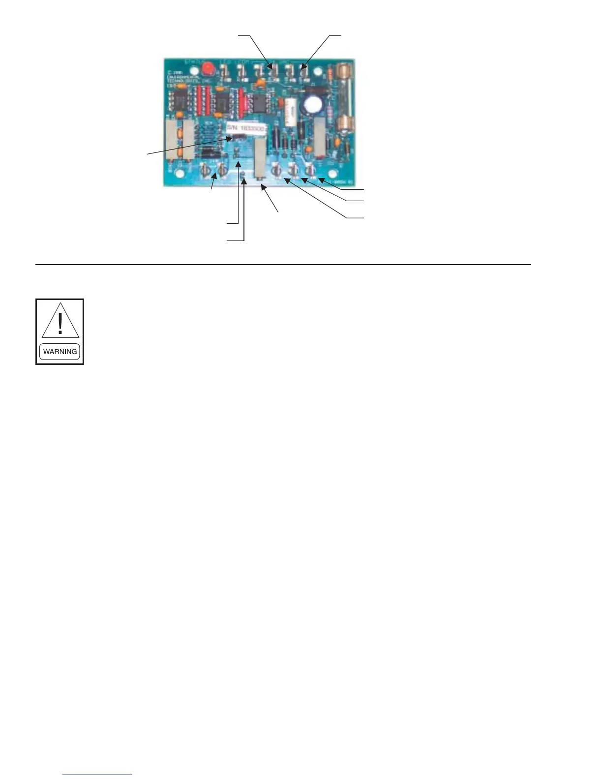
FIGURE 2 - ETPWM BOARD LAYOUT
24 volts AC
16A&B
24 volts A/C
15A&B
“G” activation line
Signal common
PWM outputManual speed
adjustment
Common test loop
VDC test loop
Analog input 2-10 VDC
Remote
Manual
umper
LD13841