JOHNSON CONTROLS
6
FORM ET130.13-NOM3 (708)
While viewing the damper from the discharge of the
equipment, disengage the actuator by depressing the
manual override button on the side of the actuator and
rotate the shaft fully. The damper should close fully and
there should be no gaps between the damper gasketing
and the inside of the valve.
Units equipped with ECM or 1 horsepower motors will
ship from the factory with a removable motor / wheel
support installed in the fan housing. It is imperative that
this shipping support be removed prior to equipment
startup or damage may result to both the motor and the
wheel. A label will be affi xed to the outside of the unit
next to the power entry point, to identify the presence
of this shipping insert.
Manually rotate the fan wheel to assure that there are
no obstructions within the fan housing.
Equipment supplied with ECM mo-
tors, backward or reverse rotation of
the blower is detrimental to the ECM
motor.
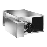
SEQUENCE OF OPERATION
All fan-powered equipment is supplied with a rectangular
discharge and comes in one of two confi gurations:
1. Parallel fl ow with hot water coils mounted on the
plenum induction air opening.
2. Series fl ow with hot water coils mounted on the
discharge opening.
Note that for either confi guration, electric heaters (if
supplied) are always mounted on the unit discharge
opening.
Parallel Flow
On parallel flow equipment, the primary air valve
delivers cooled air to the equipment’s outlet. When the
space temperature decreases beyond the control of the
primary air valve, the fan is started along with the fi rst
stage of heat. The fan delivers warm plenum air from
the controlled space to the equipment’s outlet, which
is mixed with the primary air prior to being delivered
to the space.
Either the primary air valve, fan or
both can deliver airfl ow to the occupied
space. A back draft damper is provided,
when the fan is not operating. The ef-
fi ciency of this system is the same as
standard single duct VAV equipment.
In a typical control sequence applied to parallel fl ow
equipment, the air valve is closed to a zero minimum
airfl ow before the fan is energized. After the fan has
been energized, the reheat will be energized upon a
further drop in space temperature. Therefore, little
primary air is mixed with the heated air stream.
Series Flow
Fan must be energized prior to intro-
duction of air through the primary
air valve or the possibilities exist that
the fan wheel will operate backwards
/ counter rotation.
On series fl ow equipment, the fan runs continuously
whenever the central air handler is in operation.
In response to the space temperature, the air valve
modulates the volume of primary air. The re-heat is
typically off during the air valve’s modulation. Should
the space temperature decrease to the point at which a
decrease in primary air will not maintain the desired
temperature, the reheat will be activated to increase the
discharge air temperature.
INSTALLATION
Do not use fl ow sensor, connecting
tubes, coil stubouts or damper shaft
as a handle when lifting or moving
equipment as damage may occur.
Do not handle by equipment’s heat-
ing elements, as permanent damage
will occur.