32
Burner Switch Blank INSTALLATION:
The burner switch supplied with the surround comes pre-installed and wired. This replace doesn’t require a
burner switch and it can be removed from the surround. Use the black switch blank supplied with the replace
manual to ll the hole in the surround panel where burner switch was for a cleaner appearance.
CLEANING:
NEVER CLEAN FACES WHEN THEY ARE HOT. Turn off replace and allow to fully cool.
Painted surfaces should be periodically wiped with a damp cloth. Plated surfaces mut be free of ngerprints and
smudges prior to installation and should be cleaned with a clean soft rag and a small amount of Isopropyl
alcohol.
Secondary Installation
suRRounD paneL instaLLation:
WARNING: The surround becomes hot when the unit is operating; ensure that the unit is turned off, and that
it has cooled to room temperature before beginning this installation.
Height Width
3-Sided Surround 25” (635 mm) 39
7
/8” (1013 mm)
4-Sided Surround 31
1
/2” (800 mm) 39
7
/8” (1013 mm)
Table 10: Surround Dimensions.
Please check components supplied with this kit. If components are missing or have been damaged, contact your
dealer, distributor or courier company before starting this installation.
IMPORTANT: The panel must not seal ventilation openings in the replace.
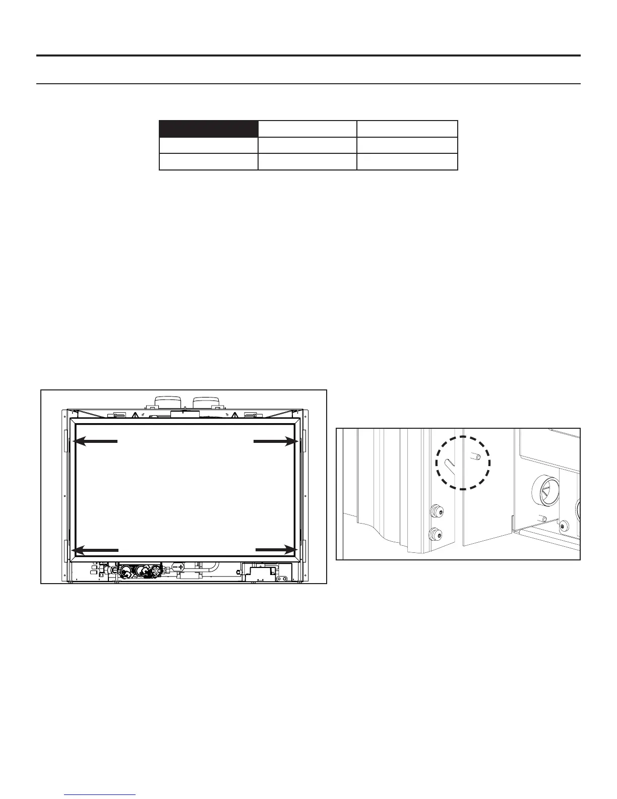
INSTALLATION (3 and 4 sided Surrounds):
Lift the face upright in front of the replace with the four hooks pointing towards the replace. Slide the hooks
over their corresponding screws (see Figures 38 & 39). Ensure the hooks are secure before releasing the
surround. The surround should be wiped with a damp cloth periodically. Screws can be tightened for a more
permanent install.
REMOVAL:
Lift the surround straight up in order to unhook the notch on the hooks from the screws. Pull the surround away
from the replace. Place the surround where it will not be damaged.
Figure 38: Screw Locations.
Figure 39: Screw and Hook Close-Up.
Access Panel
removed for
clarity.
 Loading...