25
Initial Installation
FUEL CONVERSION:
WARNING: This conversion kit shall be installed by a qualied service technician
in accordance with the manufacturer’s instructions and all applicable codes and
requirements of the authority having jurisdiction. If the information in these instructions
is not followed exactly, a re, explosion or CO poisoning may result. The qualied service
agency is responsible for the proper installation of this kit. The installation is not proper
or complete until the operation of the converted appliance is checked as specied in the
owner’s conversion kit.
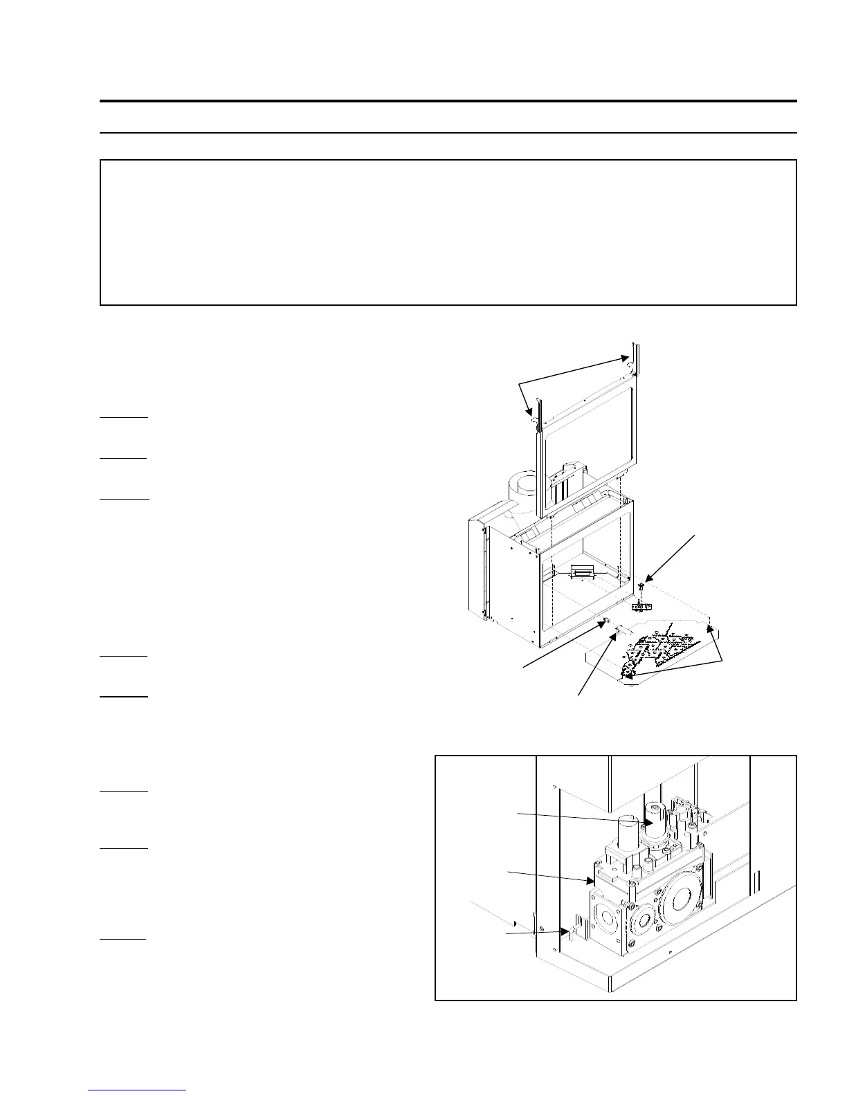
Figure 41: Gas Valve In Place on Unit.
Please read and follow these instructions. Also
please read the instruction guidelines provided
by S.I.T on how to remove and install the HI-
LOW regulator.
STEP 1. Carefully inspect all parts supplied with
this conversion kit.
STEP 2. Shut the gas off and disconnect the main
gas line from the unit.
STEP 3. Open the door by lifting the cast iron
top off of the unit. Pull the two handles
straight up to unlatch the door. Using
the two latches lift the door assembly
straight up and out of the unit. Swing
the front cast doors open or remove
them for access to the inside of the
rebox. Refer to “Routine Maintenance
and Service - Opening the Door”.
STEP 4. Carefully remove the log set and ember
material if they are installed.
STEP 5. Remove the two (2) screws (located on
the outside edges of the burner) that
hold the burner to the chassis inside
the re box, see Figure 40. Remove the
burner tray from the rebox.
STEP 6. Change the regulator on the top of the gas
valve. (Follow the instructions provided by
S.I.T)
STEP 7. To change the pilot orice, simply pull the
pilot hood straight up to access the pilot
injector. Using a
5
/32” Allen key remove the
pilot injector and replace with the proper fuel
type needed.
STEP 8. Install the new pilot injector supplied with this
conversion kit, simply screw the new injector
inside the pilot hood and reinstall pilot hood
by placing hood on the assembly lining up
the key way and snap into place.
Figure 40: Unit burner shown apart.
 Loading...