23
EN
400 V AC 3N
fan light
L N L N
L1 L2 L3 N W V U N N
WB
WM
3 4
S1
S1 N
STB
Saunasteuergerät / Control unit /
Boîtier de commande / Пульт управления
Sensorbus
Saunabus
reserviert
U V W N
PE (Gr)
Sensor
Limiter
Saunaheizgerät / Sauna heater /
Poêle de sauna / Печь для сауны
max. 9 kW
Netz / Mains / Réseau / Сеть
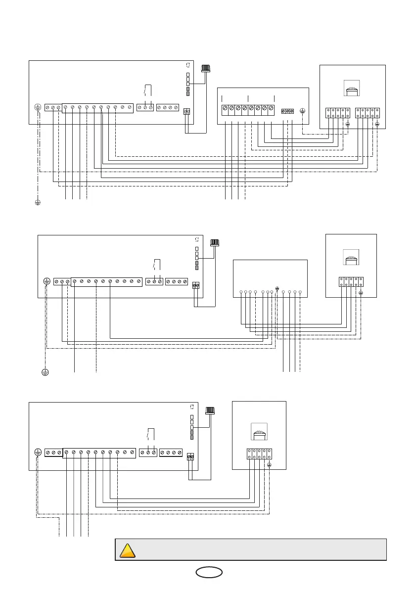
Example of a properly connected sauna system
400 V AC 3N
400 V AC 3N
fan light
L N L N
L1 L2 L3 N W V U N N
WB
WM
3 4
S1
S1 N
STB
Saunasteuergerät / Control unit /
Boîtier de commande / Пульт управления
Sensor
Saunaheizgerät / Sauna heater
Sensorbus
Saunabus
reserviert
V N S1
MAINS OVEN LSG
NL1 L2 L3 N W V U
Leistungsschaltgerät LSG 09R
U1 V1 W1 N1
U V W N
PE
(GR)
Limiter
PE
(GR)
PE
(GR)
single-circuit connection
two-circuit connection
230 V AC 3N
fan light
L N L N
L1 L2 L3 N W V U N N
WB
WM
3 4
S1
S1 N
STB
Saunasteuergerät / Control unit /
Boîtier de commande / Пульт управления
Sensorbus
Saunabus
reserviert
Saunaheizgerät / Sauna heater
U V W N
PE
U V W N
L1 L2 L3 N
S1 V N
Leistungsschaltgerät
Power extension unit
400 V AC 3N
Sensor
Limiter
single-circuit connection
LSG 18
Caution! Always make certain to include neutral conductor N clamp!
10,5 / 12 / 15 kW
10,5 / 12 / 15 kW
9 / *10,5 kW
*Modication of the wiring to the
single-circuit connection possible, if
a control unit with switching capa-
city 10,5 kW by max phase load 16A
is used.