INSTALLATION – SETUP AND OPTIONS
INPUT SELECTION
CAUTION:
Only change switch positions when the amplier is turned off.
Each channel is capable of delivering the source from a dedicated Line-In or the Global-Input by changing the
Line-In/ Global In switch.
POWER CONNECTION
Plug the supplied power cord into the amplier and to
a polarized wall outlet or appropriate surge protector.
CAUTION: DO NOT plug the amplier’s power cord into a switched
outlet, such as what is provided on some Surround Receivers. If you
wish to have the amplier turn on when the Receiver is powered up,
use the 12V trigger jack.
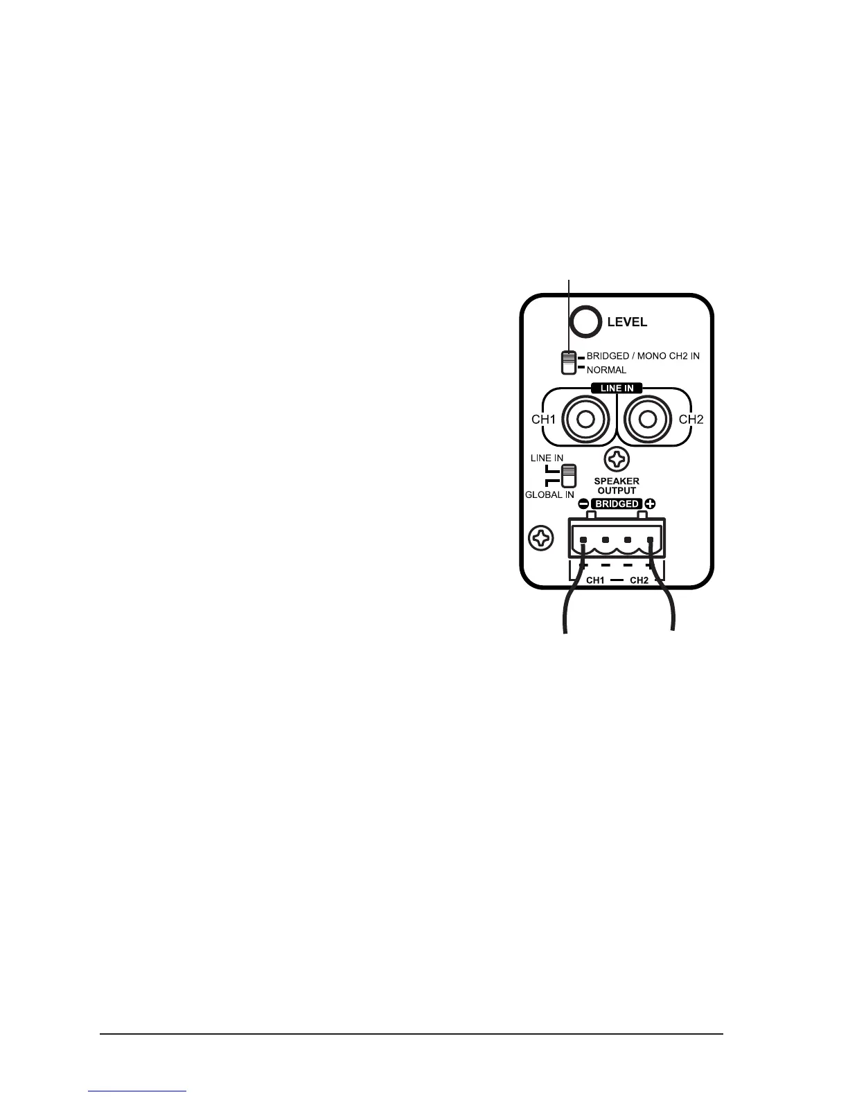
BRIDGING CHANNELS
There are situations when you may wish to combine two
channels into one through a process known as bridging.
The output of the two combined channels can then be
used to power one speaker. To bridge two adjacent
channels, rst make sure that the amplier is powered
down, and then move the switch to the “Bridged/Mono”
position. The speaker must be connected to the positive (+)
position of the removable terminals as indicated in the
illustration to the right. All input selection and volume
settings for bridged channels will be controlled by the
RED channel. DO NOT connect more than one speaker
to the outputs of the bridged channel.
NOTE: 8-ohm minimum when using bridge mode
OPERATION
POWER SWITCH/ LED
The Power switch on the front panel of the amplier will turn off the amplier no matter what state the front Power button is in.
When the amplier is on, the POWER LED will be blue. Refer to the “Power Mode” section for further information.
ZONE LED INDICATORS
When lit, the LED section on the front panel indicates that the amplier is operating. Each Zone (or pair of channels) has one
bi-color LED assigned to it. Operation is normal when the LED is blue. A red LED indicates a short in one of the speaker wires
connected for that zone. When power is on and the LED is not lit, this indicates the zone is not operating.
LEVEL ADJUSTMENT
The level adjustments on the back panel of the amplier can be used to easily adjust the level of each channel pair. One
great use for this feature is to limit the volume level in an area, such as a child’s room or guest area. Be sure set the volume
at a level that does not clip or cause distortion when the volume is at the maximum level. This can cause damage to the
speakers and the amplier.
7
Wires from Speaker
(+)(-)
Observe correct connection and
polarity when bridging channels.
Switch in bridged mode
 Loading...