U Page 18
Digital controller RK 4004
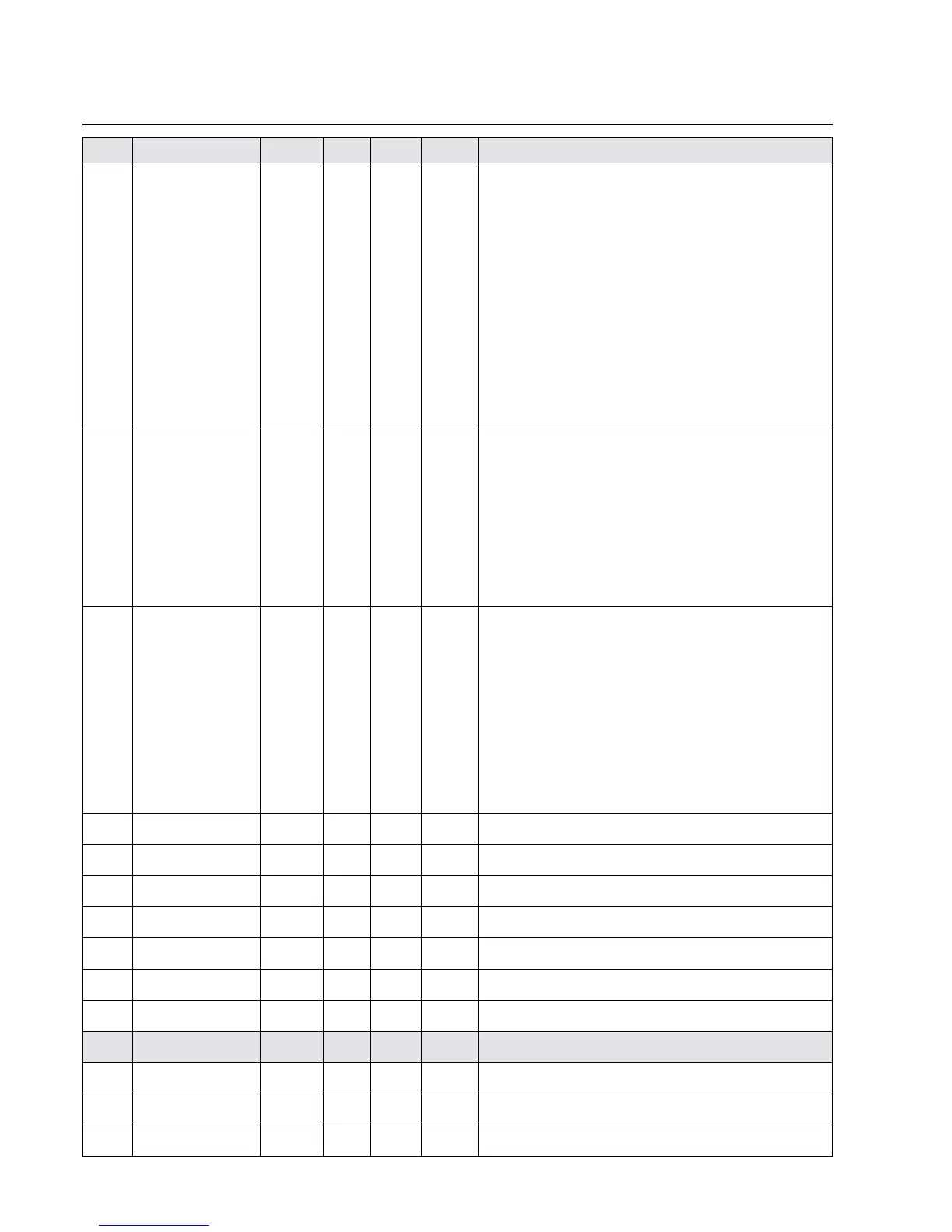
No. Name Default Min. Max. Unit Description
.9.7. >function config 1 0801 0000 FFFF System configuration1
[X] Frame limit check 0x0001
[ ] N~ / M control 0x0002
[ ] Center direct 0x0004
[ ] Ref on power on 0x0008
[ ] Watch webedge R 0x0010
[ ] Watch webedge L 0x0020
[ ] Photo on autokey 0x0040
[ ] Sens. err. > Center 0x0080
[ ] MCP active 0x0100
[ ] Auto. SensorFree 0x0200
[ ] Support 2 motor 0x0400
[X] Weboffset 1/10 mm 0x0800
[ ] Weboffset inverted 0x1000
[ ] Defect detection 0x2000
[ ] ext. system mode 0x4000
[ ] RE 1721 0x8000
.9.8. >function config 2 0000 0000 FFFF System configuration 2
(*) No Controller output 0x0000
( ) N-target -> CAN 0x0001
( ) Delta N -> CAN 0x0002
( ) Pos-target -> CAN 0x0003
( ) Delta Pos -> CAN 0x0004
( ) I-target -> CAN 0x0005
[ ] Disable I loop 0x0008
[ ] Send targetpos. 0x0010
[ ] Lock webspeed 0x0020
[ ] Start AUTO slow 0x0040
.9.9. >operatorkey config 0000 0000 FFFF Operator key
[ ] use all sensors 0x0001
[ ] Auto -> take photo 0x0002
[ ] force support free 0x0004
[ ] Cente -> supp. free 0x0008
[ ] unused sup. free 0x0010
[ ] no edge -> sens free 0x0020
[ ] sens sel. direct 0x0040
[ ] emergency sensor L 0x0080
[ ] emergency sensor R 0x0100
(*) lost web: ---- 0x0000
( ) lost web: Center 0x1000
( ) lost web: Manual 0x2000
1.0.0. reserved 100 not assigned at present
1.0.1. delaytime 1 1.0 0.0 10.0 s Delay time 1 (for switching to emergency sensor)
1.0.2. delaytime 2 1.0 0.0 10.0 s Delay time 2 (for switching to main sensor)
1.0.3. subsystem 0 adress 00 00 7F hex Serial bus card 0 address
1.0.4. subsystem 1 adress 00 00 7F hex Serial bus card 1address
1.0.5. subsystem 2 adress 00 00 7F hex Serial bus card 2 address
1.0.6. subsystem 3 adress 00 00 7F hex Serial bus card 3 address
1.0.7. • calibration Parameter title
1.0.8. calib. UDC 1.00 0.80 1.20 Operating voltage calibration
1.0.9. offset. I-act 0 -50 50 Motor current measurement offset
1.1.0. calib. I-act 1.00 0.80 1.20 Motor current measurement calibration