EasyManua.ls Logo

EPOS Odysse - Page 43

EPOS Odysse
58 pages
Print Icon
To Next Page IconTo Next Page
To Previous Page IconTo Previous Page
Loading...
43
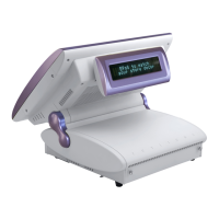
Jumper Setting for I/O Board
JP1 and JP2 control how the COM port connectors are configured. These jumpers
are located on the bottom of the I/O Connector Board and can be accessed
without terminal disassembly. Tilt the terminal and Replace the Jumper Cover
Plate (1 screw) on the bottom of the terminal to gain access to the jumpers.
1. COM1/COM2/Cash Drawer DC Power Jumper Setting: JP1 (SHORT)
Cash Drawer COM2 COM1
1-2
3-4
5-6
7-8
9-10
11-1
2
13-1
4
15-1
6
17-1
8
19-2
0
21-2
2
23-2
4
25-2
6
27-2
8
29-3
0
31-3
2
33-3
4
NC
+24
V
+24
V
+12
V
+12
V
+12
V
+5V
RI
+12
V
+5V
DCD
+12
V
+5V
RI
+12
V
+5V
DCD
PIN9 PIN1 PIN9 PIN1
Factory Default Setting
2. COM3/COM4 DC Power Jumper Setting: JP2 (SHORT)
COM4 COM3
1-2 3-4 5-6
7-8 9-10
11-12
13-14
15-16
17-18
19-20
21-22
23-24
+12V
+5V
RI
+12V
+5V
DCD
+12V
+5V
RI
+12V
+5V
DCD
PIN9 PIN1 PIN9 PIN1
Factory Default Setting
JP2 JP1
2
1
34
33
24
23
2
1