LQ-2180 Revision A
Appendix Connector Summary 51
7.2 Connector Summary
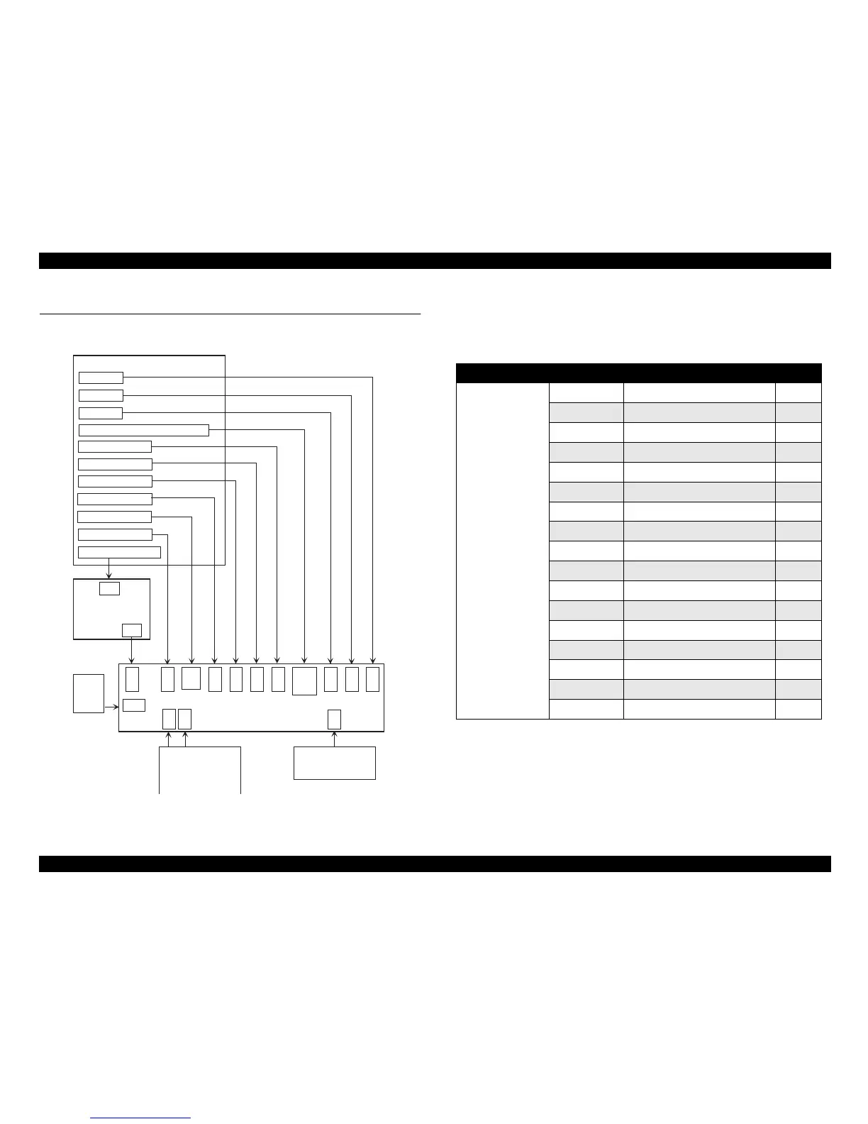
The following figure shows how primary components are connected.
Figure 7-1. Cable Connections
The table below shows the cable alignment of the C272 Main Board.
Table 7-8. C272 Main Board Connection
Printer M echanism
PG Sensor
R elease Lever P osition Sensor
PE- R ear S ensor
PE- Front Sensor
H P Sensor
PW Sensor
Printhead
C ase O pen Sensor
CN3
CN8
CN9
P F M o to r
CR Motor
CN2
CN1
CN14
CSF
CN1
Host
Computer
P a ra lle l I/F
CN2
O p tio n I/F
C165PNL Board
Fan
CN15
CN17
CN7
CN4
CN6
CN5
CN13
CN11
CN10
CN12
CN16
C272MAIN Board Assem bly
C166PSB/PSE
B oard
Board Connector Function Pins
C272 MAIN Board
CN1 Parallel interface 36
CN2 Type B interface 36
CN3 C165 PSB/PSE board assembly 12
CN4 HP sensor 3
CN5 Rear PE sensor 3
CN6 Front PE sensor 2
CN7 TOP sensor 4
CN8 Printhead (F) 18
CN9 Printhead (R) 16
CN10 PF motor 4
CN11 CR motor 5
CN12 Release lever position sensor 1 2
CN13 PG sensor 2
CN14 CSF 10
CN15 PNL board assembly 22
CN16 Release lever position sensor 2 2
CN17 Fan 2
http://www.4008109977.com guangzhou epson service :020-84207330

 Loading...