Disassembly and Assembly
EPSON Stylus COLOR 400 Service Manual
-
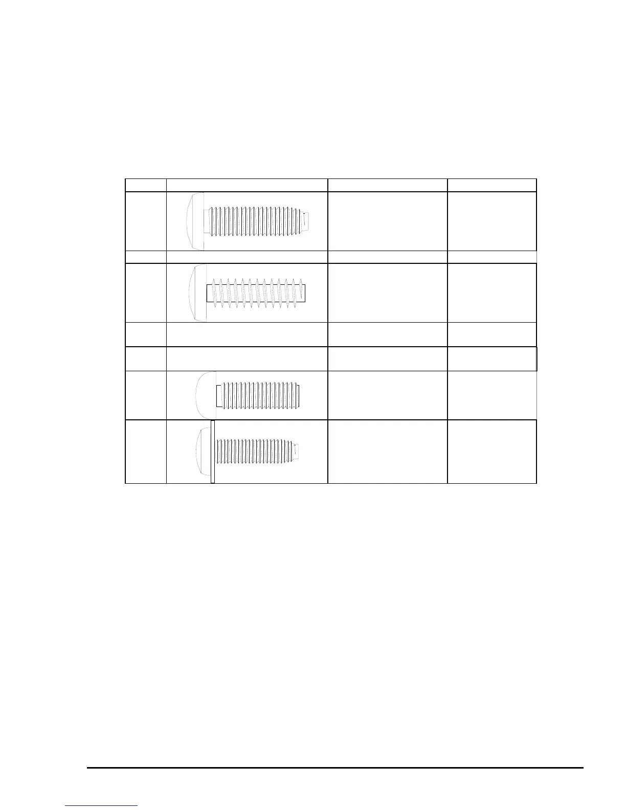
3.1.3 Specifications for Screws
Table 3-2 below shows and describes screws used in this printer. During assembly and disassembly, verify
the locations of different types of screws by referring to the table below. The screw number in the text
corresponds to the number (No.) in the table below.
No. Body Name Size
1
(+) Bind, S-tight M3 x 6
2 (+) Bind, S-tight M3 x 10
3
(+) Bind, P-tight
(CBP tight)
M3 x 6
4 (+) Bind, P-tight
(CBP tight)
M3 x 10
5 (+) Bind, P-tight
(CBP tight)
M3 x 8
6
(+) Pan head
(CP)
M3 x 4
7
(+) Bind, S-tight, Sems
R2
(CBS Sems)
M3 x 6
Table 3-2. Screw Characteristics
 Loading...


