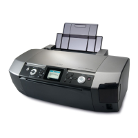
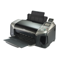
EPSON Stylus Photo R260/R265/R270, R360/R380/R390 Revision B
Disassembly/Assembly Removing Exterior Parts/Components 69
4.2.6 Panel Unit
Parts/Components need to be removed in advance
Paper Support / Printer Cover / Front Cover / Right Housing / Left Housing / USB
Housing / Upper Housing
Removal procedure
1. Disconnect the two FFCs from CN3 and CN4 connectors on the Main Board.
(disconnect CN5 only for the R260/R265/R270)
Figure 4-23. Removing the Connectors (Panel Unit)
2.
Slide the Panel while pulling it upwards and disengage the two hooks. If the
hooks do not disengage, insert a flathead screw driver into the hole of the Front
Housing positioning rib from the backside of the panel, to disengage the two
hooks ( ).
3. Slide the Panel Unit upward to remove it.
Figure 4-24. Removing the Panel Unit
C A U T I O N
Take extra care to avoid injury from sharp metal edges. Before
starting, see the page given below to check the dangerous edges.
•“4.1.8 Sharp Metal Edges (Danger!)” (p.62)
CN3
CN4
Main Board
Panel Unit
CN5
Main Board
R360/R380/R390
R260/R265/R270
Panel Unit
When reinstalling the Panel Unit, engage the four tabs by sliding
the unit downward, and insert the two ribs beside left and right
hooks into grooves until the hooks are securely engaged.
Figure 4-25. Reinstalling the Panel Unit
Removal Direction
Screw Driver
Panel Unit
Slide, while pulling
upward and
disengage the hook
[Backside]
Disengage the
hook
Mounting Direction
: Tab
: Hook
Slit
Rib
Mounting Direction
Panel Unit

 Loading...


