EPSON Stylus Photo R260/R265/R270, R360/R380/R390 Revision B
Disassembly/Assembly Disassembly of the Printer Mechanism 92
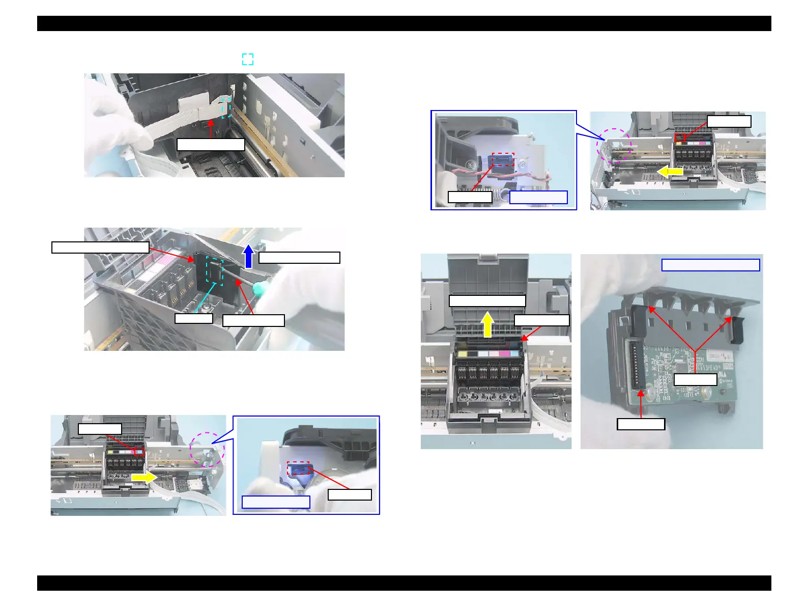
3. Disconnect the FFC from the connector ( ) on the Head Board.
Figure 4-96. Removing the FFC for CSIC
4. While disengaging the hook of the Head FFC Cover Inner with a flathead
screw driver, slide the Head FFC Cover Inner upward and remove it.
Figure 4-97. Removing the Head FFC Cover Inner
5. Move the CR Unit to its home position.
6. Insert a flathead screw driver through the hole on the right rear of the Main
Frame, and disengage the hook (1) of the CSIC Assy.
Figure 4-98. Removing the CSIC Assy (1)
7. Move the CR Unit to the left (the opposite side to the home position).
8. Taking care not to scratch the cables, insert a flathead screw driver through
the hole on the left rear of the Main Frame, and disengage the hook (2) of the
CSIC Assy.
Figure 4-99. Removing the CSIC Assy (2)
9. Slide the CSIC Assy upward to remove it.
Figure 4-100. Removing the CSIC Assy (3)
FFC for CSIC
Removal Direction
Screw Driver
Hook
Head FFC Cover Inner
Hook (1)
[Right rear side]
Hook (1)
Hook (2)
[Left rear side]
Hook (2)
CSIC Assy
Removal Direction
Rear side of CSIC Assy
Connector
Hook
 Loading...


