Confidential
Disassembly/Reassembly Disassembly/Reassembly Procedures 27
WF-2540 / WF-2530 / WF-2520 / WF-2510 / WF-2010 series
Revision B
2.2 Disassembly/Reassembly Procedures
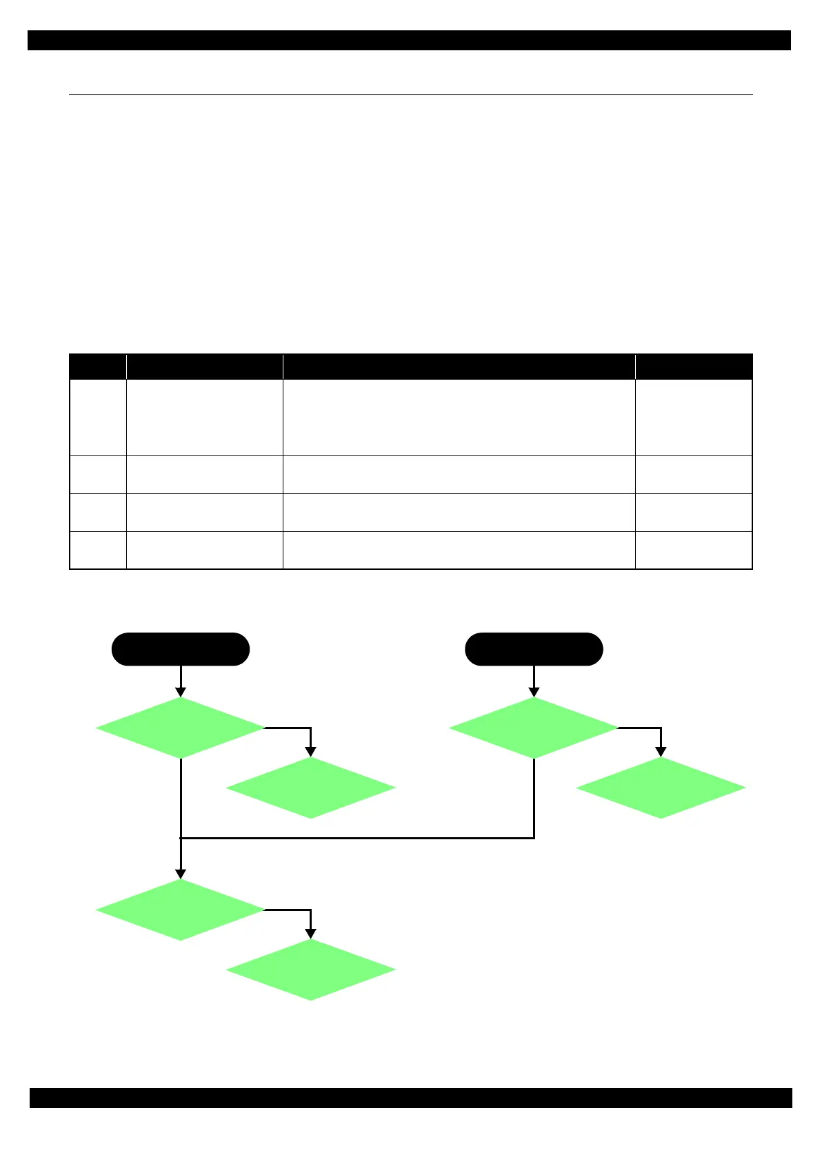
This section describes procedures for disassembling the parts/units in a flowchart format. For some parts/units,
detailed procedures or precautions are provided (accordingly indicated by icons and cell's color). Refer to the
explanations in the example chart below and perform an appropriate disassembling and assembling procedure.
(See "2.3 Detailed Disassembly/Reassembly Procedure for each Part/Unit (p40)".)
For routing cables, see "2.4 Routing FFCs/cables (p48)".
2.2.1 Configuration
This section describes the configuration of the disassembly flowchart.
The disassembly flowchart is divided into the “Multifunction Printer specific parts”, “Singlefunction Printer
specific parts”, “Common Printer Mechanism”, and the “Unit/Assy”. Each section describes the following
contents.
Figure 2-7. Configuration
No. Item Description Compatible Model
2.2.2.1
Multifunction Printer
specific parts
Describes the disassembly flowchart for the Multifunction Printer-
specific parts
WF-2540 Series
WF-2530 Series
WF-2520 Series
WF-2510 Series
2.2.2.2
Singlefunction Printer
specific parts
Describes the disassembly flowchart for the Singlefunction Printer-
specific parts
WF-2010 Series
2.2.2.3
Common Printer
Mechanism
Describes the disassembly flowchart for the Printer Mechanism
common in the Multifunction Printer and Singlefunction Printer
Common to all
models
2.2.2.4 Unit/Assy Describes the disassembly flowchart for the Unit/Assy components
Common to all
models
START
Multifunction Printer
START
Singlefunction Printer
2.2.2.4
Unit/Assy
2.2.2.1
Multifunction Printer
specific parts
2.2.2.4
Unit/Assy
2.2.2.3
Common Printer
Mechanism
2.2.2.4
Unit/Assy
2.2.2.2
Singlefunction Printer
specific parts