WF-2540 / WF-2530 / WF-2520 / WF-2510 / WF-2010 series Revision B
Disassembly/Reassembly Detailed Disassembly/Reassembly Procedure for each Part/Unit 41
Confidential
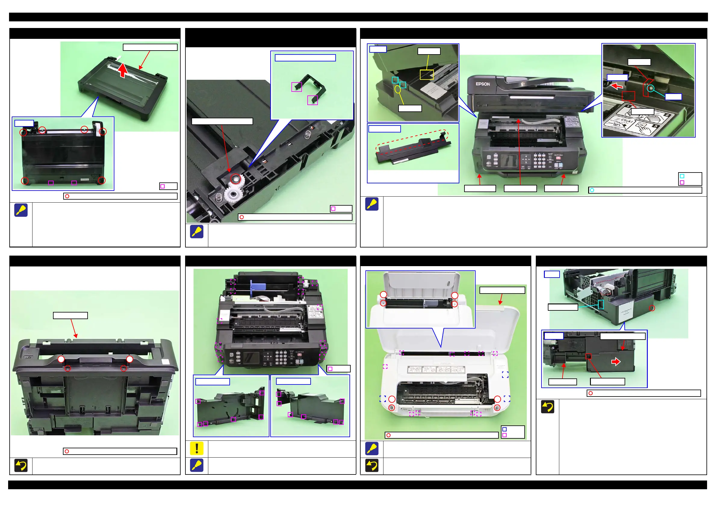
Scanner Housing Upper (Scanner compatible model)
When removing the Scanner Housing Upper from the Scanner
Housing Lower Assy, follow the procedure below.
1. Remove the screws (x6) on the bottom of the Scanner Unit.
2. Release the ribs (x2) of the Scanner Housing Upper, and
remove the Scanner Housing Upper in the direction of the
arrow with the document glass upward.
C.B.P-TITE SCREW 3x10 F/ZN-3C (6 ± 1 kgf·cm)
Rib
Scanner Housing Upper
Scanner Motor Gear Cover
(Scanner compatible model)
Remove the Scanner Motor Gear Cover by removing the screw
securing the Scanner Motor Gear Cover to release the hooks (x2) of
the Scanner Motor Gear Cover.
C.B.P-TITE SCREW 3x10 F/ZN-3C (6 ± 1 kgf·cm)
Hook
Scanner Motor Gear Cover
Housing Rear (Multifunction Printer)
When removing the Housing Rear, follow the procedure below.
1. Remove the screw (x1) of the Housing Rear.
2. Press the section A on the Housing Left and release the dowels (x2) of the Housing Left from the Housing Rear, and lift the rear side of the
Housing Rear slightly to release the section B from the Housing Left.
3. Pull and turn the section C of the Housing Rear slightly to the front to release it from the gap between the Housing Right and Frame Base.
4. Slide the Housing Rear in the direction of the arrow to release the section D, and remove the Housing Rear while avoiding the Hopper and
Scanner Unit.
C.B.P-TITE SCREW 3x10 F/ZN-3C (6 ± 1 kgf·cm)
Section D
Section C
Step 3-4
Step 1
The section enclosed in red dotted line may be
interfered with the Hopper or the Scanner Unit.
Housing RightHousing Left
Housing Front (Multifunction Printer)
Tighten the screws in the order indicated in the figure above.
Housing Front
12
C.B.P-TITE SCREW 3x10 F/ZN-3C (6 ± 1 kgf·cm)
Housing Left / Housing Right
When releasing the hooks (x14) of the Housing Left/Housing
Right, be careful not to damage the hooks (x14).
Release the hooks shown above when removing the Housing Left/
Housing Right.
Housing Upper Assy (Singlefunction Printer)
Remove the Housing Upper Assy by releasing the hooks (x3) and
ribs (x10) shown in the figure above.
Tighten the screws in the order indicated in the figure above.
2
Housing Upper Assy
Hook
Rib
1
C.B.P-TITE SCREW 3x10 F/ZN-3C (6 ± 1 kgf·cm)
Waste Ink Pad Assy
When installing the Waste Ink Pad Assy, follow the procedure below.
1. Place the Waste Ink Pad Assy under the Frame Base.
2. Slide the Waste Ink Pad Assy in the direction of the arrow to
align the hole of the Waste Ink Pad Assy with the hook of the
Frame Base.
3. Confirm the following first, and then tighten the screw to
secure the Waste Ink Pad Assy.
• The rib of the Waste Ink Pad Assy is correctly inserted into
the hole of the Frame Base.
• The Waste Ink Pad Assy is secured firmly with the hook of
the Frame Base.
Bottom
Hook and holeFrame Base
Waste Ink Pad Assy
Rear
Rib and hole
C.B.P-TITE SCREW 3x10 F/ZN-3C (6 ± 1 kgf·cm)