WF-2540 / WF-2530 / WF-2520 / WF-2510 / WF-2010 series Revision B
Disassembly/Reassembly Detailed Disassembly/Reassembly Procedure for each Part/Unit 47
Confidential
Cap Lever / Cap Assy
When installing the Cap Lever/Cap Assy, follow the procedure below.
1. Attach the Cap Lever to the Frame Base, and attach one end of the Extension Spring 0.65 to the hook of the Frame Base.
2. Connect the tube of the Pump Unit to the joint on the bottom of the Cap Assy. Then, viewing from the side, confirm the marking (10 ± 1 mm
from the tube end) on the tube is covered by the Cap Slider.
3. Insert the shaft A of the Cap Assy through the hole of the Cap Lever to the hole A of the Frame Base.
4. Insert the shaft B of the Cap Assy through the cutout of the Frame Base and to the hole B of the Frame Base.
5. Insert the shaft C of the Cap Assy to the hole C of the Frame Base.
6. Using a “spring hook jig” (p 20), attach the other end of the Extension Spring 0.65 to the hook of the Cap Assy.
7. Attach the Extension Spring 1.329 to the hooks of the Cap Lever and Frame Base.
Cap Lever
Extension Spring 1.329
Cap Assy
Extension Spring 0.65
Hook of Cap Assy
Hook of Frame Base
Step 6
Shaft BShaft A
Shaft C
Cap Assy
Step 2
Make sure the marking (10 ± 1 mm
from the tube end) on the tube cannot
be seen when viewed from the side.
Cap Slider
CutoutHole B
Cap Lever
Frame
Base
Hole A
Hole C
Step 1, 3-5
Hook of Frame Base
Hook of Cap Lever
Step 7
Pump Unit
When installing the Pump Unit, follow the procedure below in order to prevent ink suction failure.
1. Route the Pump Tube A through the hole of the Frame Base.
2. Install the Pump Unit to the Frame Base, and route the Pump Tube A through the ribs of the Frame Base with their dashed line facing upward.
3. Secure the Pump Unit to the Frame Base with the screw (x1).
4. Route the Pump Tube B through the ribs of the Pump Unit and Frame Base, and insert it to the hole of the Frame Base up to the marking
(8
± 1 mm from tube end).
Step 4
Pump
Tube B
Marking
8 ± 1 mm
Hole of Frame Base
Hole of
Frame Base
Pump
Tube A
Step 1-2
Pump Unit
Route Pump Tube A through ribs of Frame
Base with their dashed line facing upward.
Insert Pump Tube B up to the marking (8 ± 1 mm
from tube end) to the hole of Frame Base.
C.B.P-TITE SCREW 3x10 F/ZN-3C (6 ± 1 kgf·cm)
Step 3
Frame Base
Rib
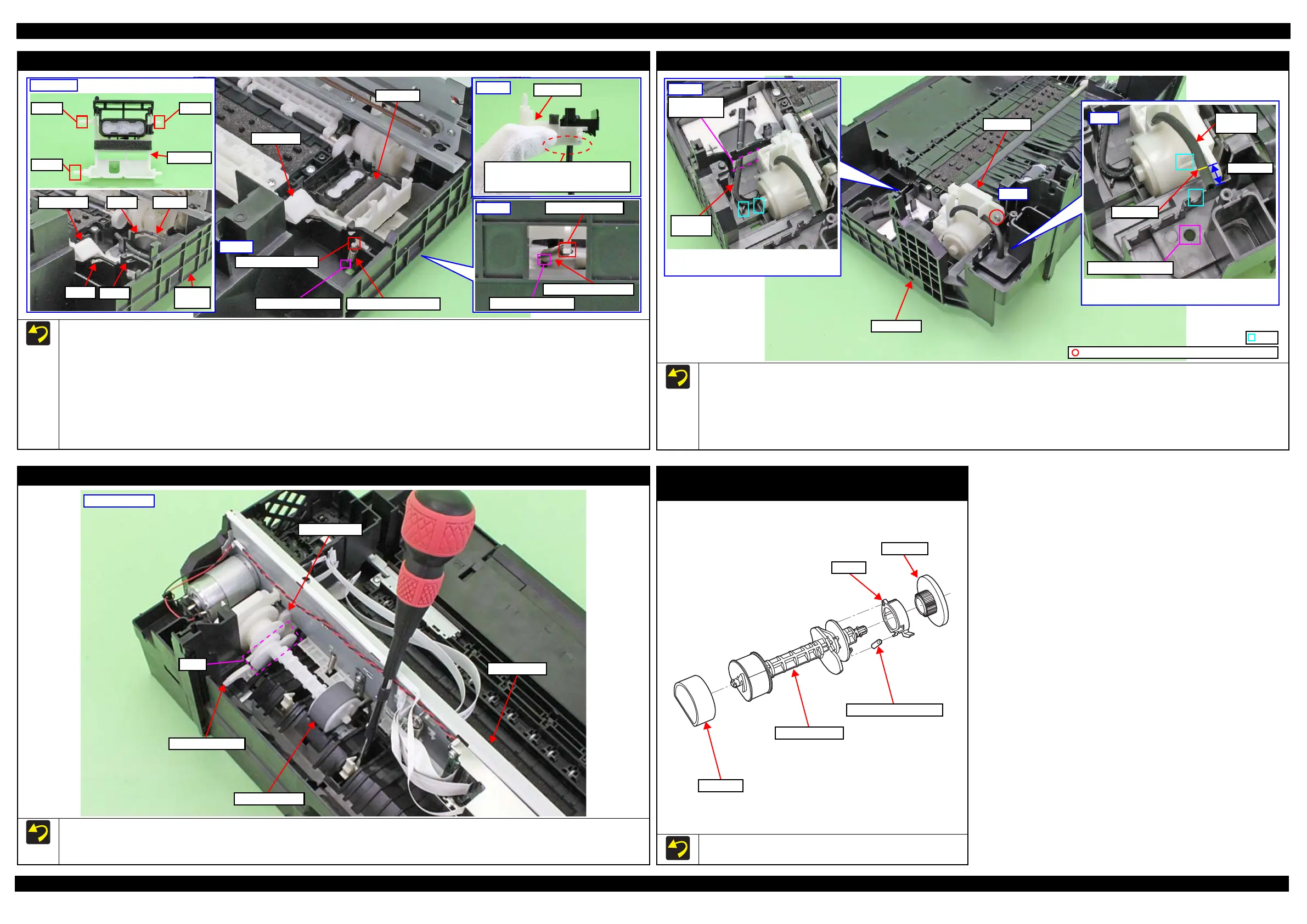
LD Roller Assy (1)
Install the LD Roller Assy with the following condition in order to avoid the Change Lever and Paper Back Lever.
Using a screw driver or the like, hold the Paper Back Lever to the rear as shown above not to let it touch the LD Roller Assy.
Push the Change Lever to the front to keep it in the hole of the Main Frame.
LD Roller Assy
Paper Back Lever
Change Lever
Cam
Main Frame
Rear of printer
Spur gear / Extension Spring 0.137 /
Clutch / LD Roller shaft
Install Spur gear/Extension Spring 0.137/Clutch/LD Roller shaft as
shown in the figure above.
Extension Spring 0.137
Clutch
Spur gear
LD Roller Shaft
LD Roller