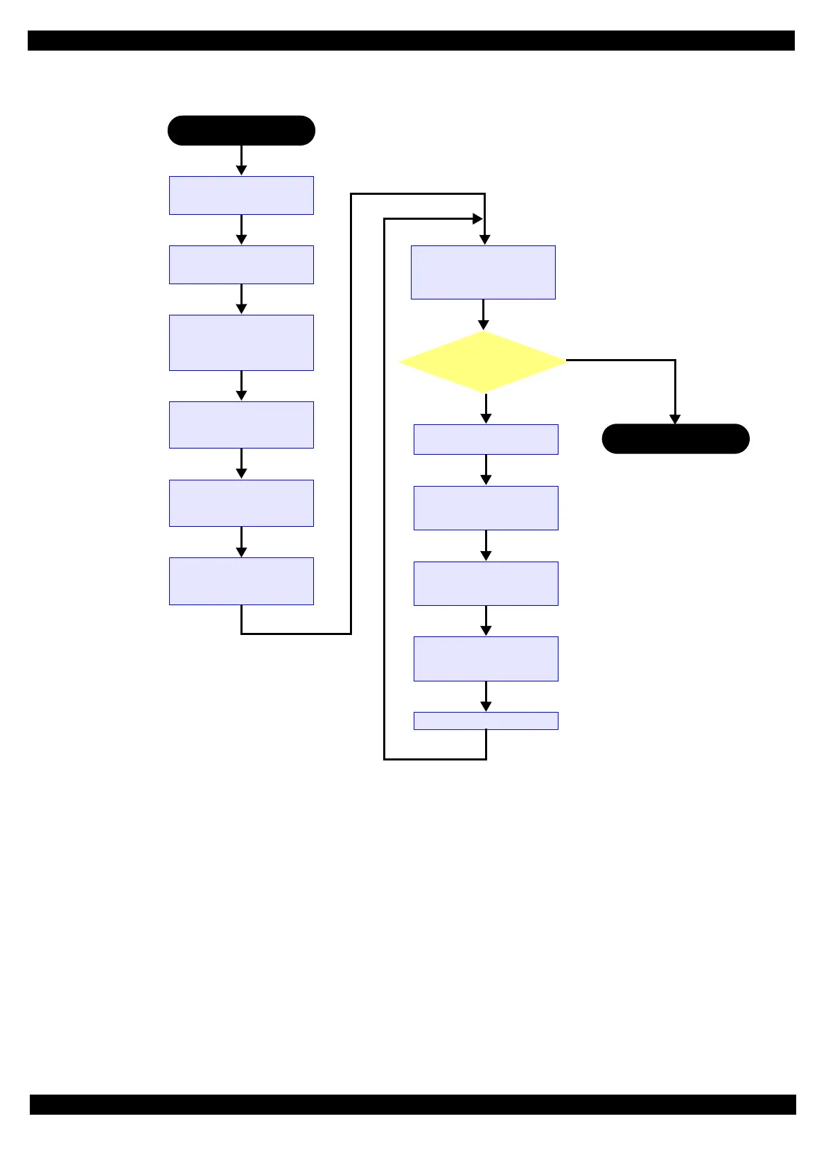
Figure 3-13. Head angular mecha adjustment procedure flowchart
Start the printer with
“Printer Inspection Mode”
Start the adjustment
Confirm the adjustment pattern
Line space is equal?
Print the adjustment pattern
from Adjustment program
Check the adjustment
pattern, and forecast the
adjustment value when the
line space becomes equal.
Release the Carriage Lock
and move the Carriage unit
to center of the printer.
Set the Spacer (5mm)
between the star wheel assy
and CR unit.
Rotate the adjustment dial by
forecast value, and tighten
the screws.
Start the printer with
“Printer Inspection Mode”,
and printer the adjustment
pattern.
Confirm the misalignment
direction.
Release the Carriage Lock
and move the Carriage unit
to center of the printer.
Set the Spacer (5 mm)
between the star wheel assy
and CR unit.
Move the Adjustment dial for
1 step to the misalignment
direction.
Tighten the screws.
Adjustment is finished.
 Loading...